Ford Ecosport: Front Suspension / Removal and Installation - Front Wheel Bearing and Wheel Hub
Special Tool(s) / General Equipment
 |
204-180
(T93P-5493-A)
Remover/Installer, Bushing TKIT-1993-FLM TKIT-1993-LM TKIT-1993-FM |
 |
204-348/3 Remover/Installer, Wheel Hub/Wheel Bearing |
 |
205-D064
(D84L-1123-A)
Puller, Bearing |
 |
308-095 Installer, Input Shaft Bearing |
 |
308-604 Installer, Output Drive Flange Seal |
 |
308-643 Installer, Input Shaft Seal |
| Hydraulic Press | |
Removal
-
NOTE: If removing the wheel hub, a new wheel bearing must be installed.
Remove the wheel knuckle.
Refer to: Wheel Knuckle (204-01 Front Suspension, Removal and Installation).
-
NOTE: After the wheel hub is removed from the wheel knuckle, the wheel bearing must be discarded.
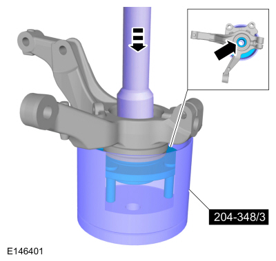
Remove the wheel hub from the wheel knuckle using the hydraulic press and special tools.
Use Special Service Tool: 204-348/3 Remover/Installer, Wheel Hub/Wheel Bearing.
Use the General Equipment: Hydraulic Press
 |
-
NOTICE: The Bearing Puller and Bushing Remover/Installer must be used to prevent damage to the hub. If the hub is damaged, a new hub must be installed.
NOTICE: Do not use heat to remove the bearing inner ring or damage to the bearing may occur.
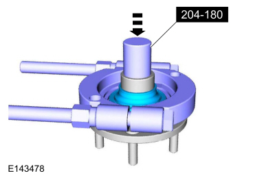
NOTE: This step may not be necessary if the wheel bearing inner race remains on the wheel bearing after removing the wheel hub.
Using the special tools remove the wheel bearing inner race from the wheel hub (if remaining).
Use Special Service Tool: 204-180 (T93P-5493-A) Remover/Installer, Bushing. , 205-D064 (D84L-1123-A) Puller, Bearing.
Use the General Equipment: Hydraulic Press
 |
-
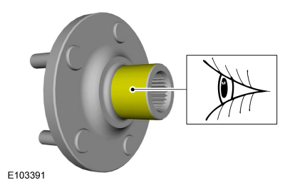
Visually check the wheel hub surfaces for abrasion.
 |
-
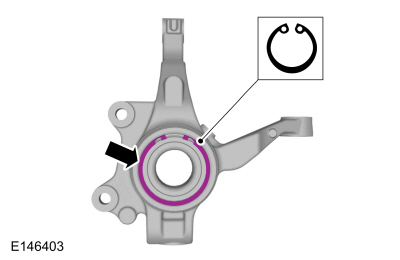
Remove the wheel bearing snap ring.
 |
-
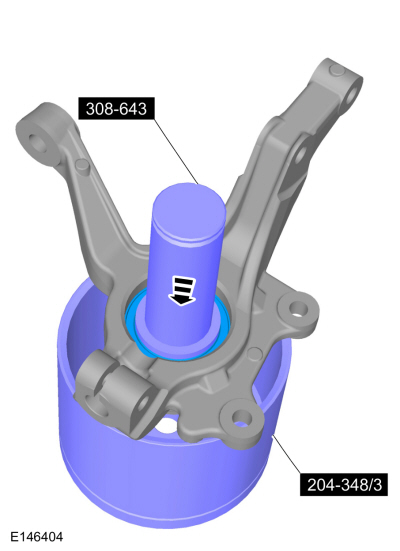
Remove the wheel bearing using the hydraulic press and special tools. Discard the wheel bearing.
Use Special Service Tool: 204-348/3 Remover/Installer, Wheel Hub/Wheel Bearing. , 308-643 Installer, Input Shaft Seal.
Use the General Equipment: Hydraulic Press
 |
Installation
-
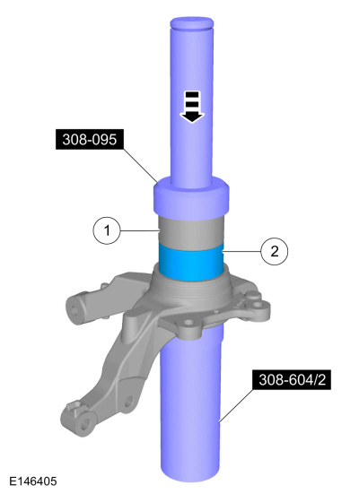
NOTICE: Make sure the wheel bearing is installed into the wheel knuckle with the wheel speed sensor ring (black in color) toward the inner face of the wheel knuckle.
NOTICE: Once the wheel bearing is installed, make sure the wheel speed sensor ring on the bearing and the sensor hole on the wheel knuckle are clean or damage to the wheel speed sensor or sensor ring may occur.
Install the wheel bearing using the hydraulic press and special tools.
Use Special Service Tool: 308-095 Installer, Input Shaft Bearing. , 308-604 Installer, Output Drive Flange Seal.
Use the General Equipment: Hydraulic Press
 |
-
NOTE: Make sure the wheel speed sensor hole in the wheel knuckle is not blocked by the snap ring. The sensor hole must be positioned between the ends of the snap ring.
Install the wheel bearing snap ring.
|
-
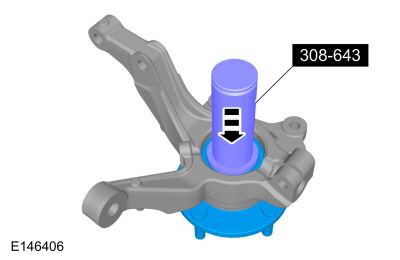
Install the wheel hub into the wheel knuckle using the hydraulic press and special tools.
Use Special Service Tool: 308-643 Installer, Input Shaft Seal.
Use the General Equipment: Hydraulic Press
 |
-
Install the wheel knuckle.
Refer to: Wheel Knuckle (204-01 Front Suspension, Removal and Installation).
 Removal and Installation - Wheel Knuckle
Special Tool(s) /
General Equipment
204-161
(T97P-1175-A)
Installer, HalfshaftTKIT-1997-LM2TKIT-1997-F/FM2TKIT-1997-FLM2
205-D070
(D93P-1175-B)
Remover, Front Wheel Hub
Tie Rod End Remover
Removal
NOTICE:
Suspension fasteners are critical parts that affect the
performance of vital components and systems...
 Disassembly and Assembly - Front Strut and Spring Assembly
Special Tool(s) /
General Equipment
Spring Compressor
Vise
Materials
Name
Specification
Motorcraft® Silicone Brake Caliper Grease and Dielectric CompoundXG-3-A
ESA-M1C200-AESE-M1C171-A
DISASSEMBLY
NOTICE:
Suspension fasteners are critical parts that affect the
performance of vital components and systems...
Other information:
Ford Ecosport 2014-2025 Service and Repair Manual: Description and Operation - Climate Control System - Vehicles With: Electronic Automatic Temperature Control (EATC) - System Operation and Component Description
System Diagram Item Description 1 HVAC control module 2 Blower motor speed control 3 Blower motor 4 Air distribution door actuator 5 Blower motor relay 6 Air inlet door actuator 7 Temperature door actuator 8 Center register air discharge temperature sensor 9 Footwel..
Ford Ecosport 2014-2025 Service and Repair Manual: Diagnosis and Testing - Pinpoint Test - DTC: B, Vehicles With: Rear Seat Side Airbag
B0002:11, B0002:12, B0002:13 and B0002:1A Refer to Wiring Diagrams Cell 46 for schematic and connector information. Normal Operation and Fault Conditions The RCM continuously monitors the driver airbag stage 2 circuits for the following faults: Resistance out of range Unexpected voltage Short to ground Faulted driver airbag If a fault is d..
Categories
- Manuals Home
- 2nd Gen Ford Ecosport Service Manual (2014 - 2025)
- Removal and Installation - Body Control Module (BCM)
- Removal and Installation - Front Seat
- Removal and Installation - Fuel Pump and Sender Unit
- Automatic Transmission - 6-Speed Automatic Transmission – 6F35
- Description and Operation - Evaporative Emissions - System Operation and Component Description
Removal and Installation - Oil Pressure Switch
Materials
Name Specification Motorcraft® Thread Sealant with PTFETA-24-B WSK-M2G350-A2
Removal
NOTE: Removal steps in this procedure may contain installation details.
With the vehicle in NEUTRAL, position it on a hoist.Refer to: Jacking and Lifting - Overview (100-02 Jacking and Lifting, Description and Operation).
If equipped, remove the bolts and the underbody shield.