Ford Ecosport: Handles, Locks, Latches and Entry Systems / Removal and Installation - Front Door Latch
Ford Ecosport 2014-2026 Service and Repair Manual / Body and Paint / Handles, Locks, Latches and Entry Systems / Removal and Installation - Front Door Latch
Removal
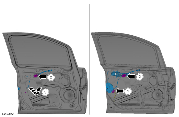
NOTE: LH side shown, RH side similar.
NOTE: Removal steps in this procedure may contain installation details.
-
Remove the front door glass run and bracket.
Refer to: Front Door Glass Run and Bracket (501-11 Glass, Frames and Mechanisms, Removal and Installation).
-
Remove the exterior front door handle.
Refer to: Exterior Front Door Handle (501-14 Handles, Locks, Latches and Entry Systems, Removal and Installation).
-
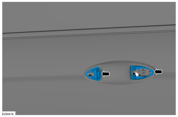
Remove the exterior front door handle gaskets.
 |
-
Remove the exterior front door handle reinforcement screw.
 |
-
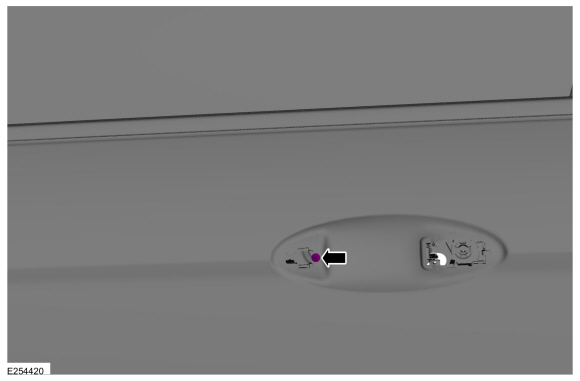
If equipped.
Remove the glass run channel fasteners.
Torque: 27 lb.in (3 Nm)
 |
-
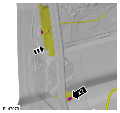
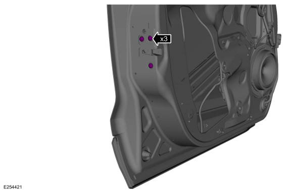
Remove the front door latch bolts.
Torque: 71 lb.in (8 Nm)
 |
-
Remove the front door latch and front door handle reinforcement as an assembly.
-
Disconnect electrical connector from the front door latch.
-
Route the interior front door handle cable through the door.
-
Remove the front door latch and front door handle reinforcement as an assembly.
-
Disconnect electrical connector from the front door latch.
 |
-
NOTE: This step is only necessary when installing a new component.
Remove the front door latch from the exterior front door handle reinforcement.
-
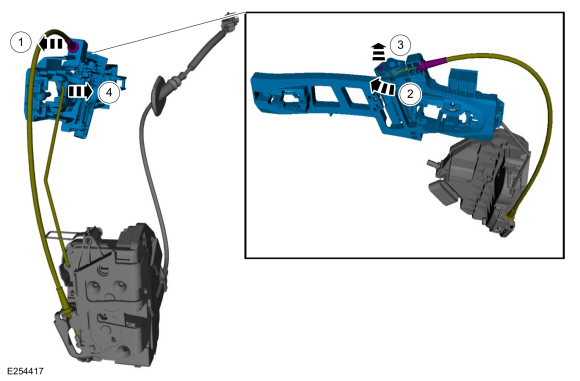
Disconnect the exterior door handle cable from the mounting bracket.
-
Route the exterior door handle cable out of the exterior front door handle reinforcement.
-
Remove the exterior door handle cable end from the exterior front door handle reinforcement.
-
Remove lock rod from the exterior front door handle reinforcement.
-
Disconnect the exterior door handle cable from the mounting bracket.
 |
-
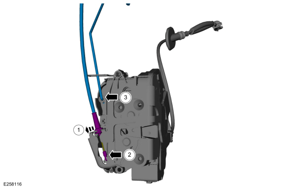
NOTE: This step is only necessary when installing a new component.
Remove the exterior door handle cable and lock rod from the front door latch.
-
Disconnect the exterior door handle cable from the mounting bracket.
-
Remove the exterior door handle cable from the front door latch.
-
Remove lock rod from the front door latch.
-
Disconnect the exterior door handle cable from the mounting bracket.
 |
-
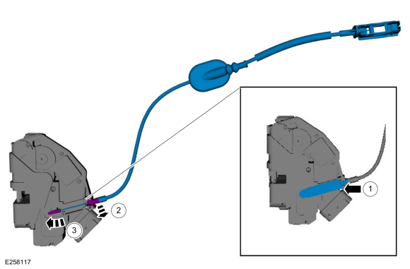
NOTE: This step is only necessary when installing a new component.
Remove the interior front door handle cable from the rear door latch.
-
Remove the cover from the interior front door handle cable.
-
Disconnect the interior front door handle cable from the mounting bracket.
-
Remove the interior front door handle cable end from the front door latch.
-
Remove the cover from the interior front door handle cable.
 |
Installation
-
To install, reverse the removal procedure.
-
If the door is equipped with one touch up/down.
Carry out the power door window initialization.
Refer to: Power Door Window Initialization (501-11 Glass, Frames and Mechanisms, General Procedures).
 Removal and Installation - Exterior Rear Door Handle Reinforcement
Removal
NOTE:
LH side shown, RH side similar.
Remove the rear door latch.
Refer to: Rear Door Latch (501-14 Handles, Locks, Latches and Entry Systems, Removal and Installation)...
 Removal and Installation - Front Door Lock Control Switch
Removal
NOTE:
LH side shown, RH side similar.
Remove the front door trim panel
Refer to: Front Door Trim Panel (501-05 Interior Trim and Ornamentation, Removal and Installation)...
Other information:
Ford Ecosport 2014-2026 Service and Repair Manual: Description and Operation - Warning Chimes - System Operation and Component Description
System Operation System Diagrams Base AM/FM Audio System Item Description 1 IPC chime arbitrator 2 Airbag warning chime 3 Message center chime 4 Belt-Minder® warning chime 5 Door ajar warning chime 6 Headlamps on warning chime 7 Low fuel warning chime 8 Perimeter alarm chime ..
Ford Ecosport 2014-2026 Service and Repair Manual: Description and Operation - Electronic Engine Controls - Component Location
Item Description 1 MAF sensor 2 CMP sensor 3 CHT sensor 4 VCT oil control solenoid 5 CKP sensor 6 HO2S sensor 7 Catalyst Monitor sensor 8 ECT sensor 9 PCM Front of Engine Item Description 1 FRP sensor 2 KS..
Categories
- Manuals Home
- 2nd Gen Ford Ecosport Service Manual (2014 - 2026)
- Diagnosis and Testing - Evaporative Emissions
- Removal and Installation - Blower Motor
- Specifications
- Service Information
- Diagnosis and Testing - Body Control Module (BCM)
Removal and Installation - Oil Pressure Switch
Materials
Name Specification Motorcraft® Thread Sealant with PTFETA-24-B WSK-M2G350-A2
Removal
NOTE: Removal steps in this procedure may contain installation details.
With the vehicle in NEUTRAL, position it on a hoist.Refer to: Jacking and Lifting - Overview (100-02 Jacking and Lifting, Description and Operation).
If equipped, remove the bolts and the underbody shield.
Copyright © 2026 www.foecosport2.com