Ford Ecosport: Front End Body Panels / Removal and Installation - Fender
Ford Ecosport 2014-2026 Service and Repair Manual / Body and Paint / Front End Body Panels / Removal and Installation - Fender
Removal
NOTE: LH shown, RH similar.
NOTE: Removal steps in this procedure may contain installation details.
-
Remove the fender splash shield.
Refer to: Fender Splash Shield (501-02 Front End Body Panels, Removal and Installation).
-
Remove the headlamp assembly.
Refer to: Headlamp Assembly (417-01 Exterior Lighting, Removal and Installation).
-
Release the retainers and remove the door frame moulding.
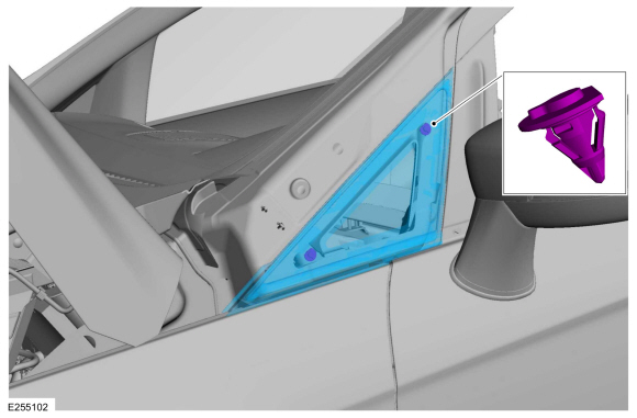 |
-
Remove the fender insulation.
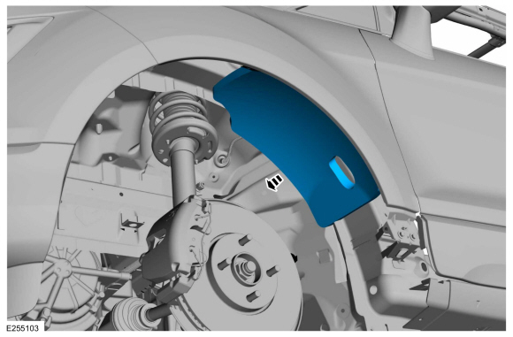 |
-
Remove the fender baffle.
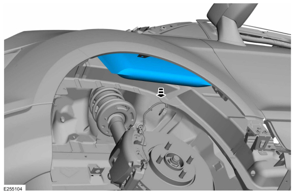 |
-
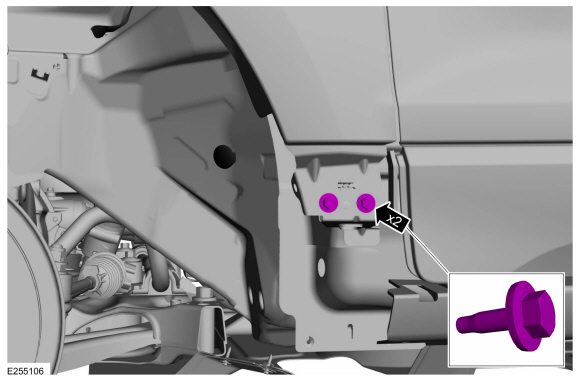
Remove bolts and front bumper to fender bracket.
Torque: 97 lb.in (11 Nm)
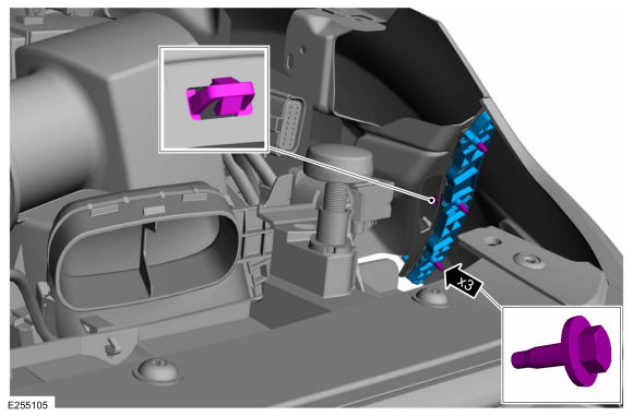 |
-
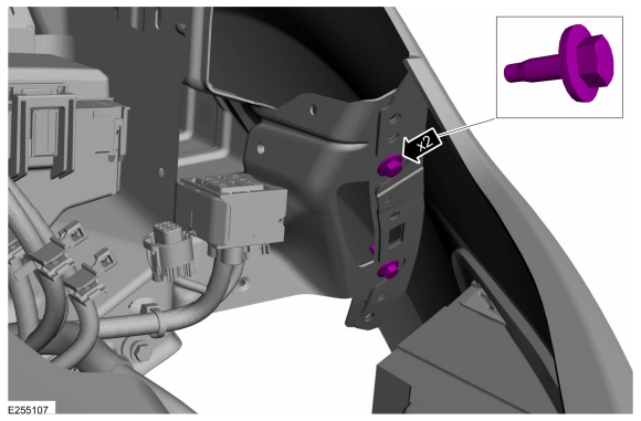
Remove the bolts.
Torque: 97 lb.in (11 Nm)
 |
-
Remove the fender mounting bracket bolts.
Torque: 97 lb.in (11 Nm)
 |
-
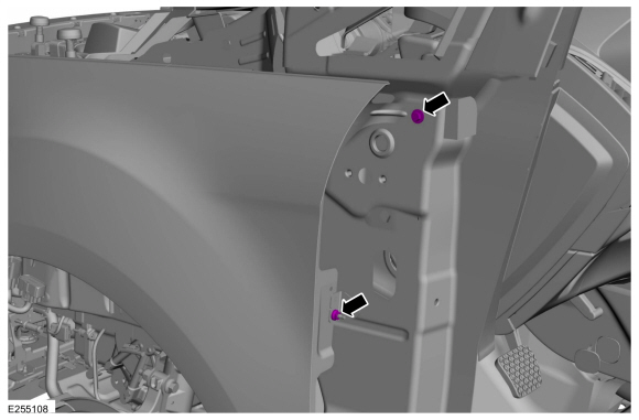
Remove the fender to front reinforcement pillar bolt and the nut.
Torque: 97 lb.in (11 Nm)
 |
-
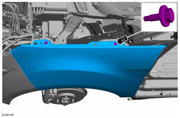
Remove the upper mounting bolts and the fender.
Torque: 97 lb.in (11 Nm)
 |
Installation
-
To install, reverse the removal procedure.
 Removal and Installation - Engine Undershield
If equipped, remove the retainers and the under body shield.
Torque:
Stage 1:
13 lb.in (1.5 Nm)
Stage 2:
22 lb...
 Removal and Installation - Hood
Removal
NOTE:
Removal steps in this procedure may contain installation details.
NOTE:
This step is only necessary when installing a new component...
Other information:
Ford Ecosport 2014-2026 Service and Repair Manual: Diagnosis and Testing - Pinpoint Test - DTC: E, Vehicles With: Rear Seat Side Airbag
B0011:11, B0011:12, B0011:13, B0011:1A Refer to Wiring Diagrams Cell 46 for schematic and connector information. Normal Operation and Fault Conditions The RCM continuously monitors the passenger airbag stage 2 circuits for the following faults: Resistance out of range Unexpected voltage Short to ground Faulted passenger airbag If a fault i..
Ford Ecosport 2014-2026 Service and Repair Manual: General Procedures - Transfer Case Fluid Level Check
Materials Name Specification Motorcraft® SAE 75W-85 Premium Synthetic Hypoid Gear LubricantXY-75W85-QL WSS-M2C942-A Follow the health and safety precautions. Refer to: Health and Safety Precautions (100-00 General Information, Description and Operation). With the vehicle in NEUTRAL, position it on a hoist. Refer to: J..
Categories
- Manuals Home
- 2nd Gen Ford Ecosport Service Manual (2014 - 2026)
- General Procedures - Transmission Fluid Level Check
- Diagnosis and Testing - Evaporative Emissions
- Description and Operation - Jacking and Lifting - Overview
- Removal and Installation - Starter Motor
- Removal and Installation - Body Control Module (BCM)
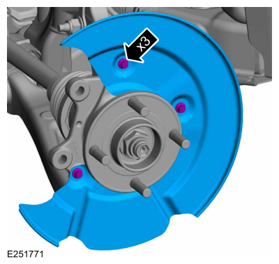
Removal and Installation - Brake Disc Shield
Removal
NOTE: Removal steps in this procedure may contain installation details.
Remove the brake disc.Refer to: Brake Disc (206-03 Front Disc Brake, Removal and Installation).
Remove the bolts and brake disc.
Torque: 80 lb.in (9 Nm)
Copyright © 2026 www.foecosport2.com