Ford Ecosport: Engine - 2.0L Duratec-HE (129kW/175PS) / General Procedures - Valve Clearance Adjustment
Special Tool(s) / General Equipment
| Feeler Gauge |
Check
-
Remove the valve cover.
Refer to: Valve Cover (303-01C Engine - 2.0L Duratec-HE (129kW/175PS), Removal and Installation).
-
Remove the RH front wheel and tire.
Refer to: Wheel and Tire (204-04A Wheels and Tires, Removal and Installation).
-
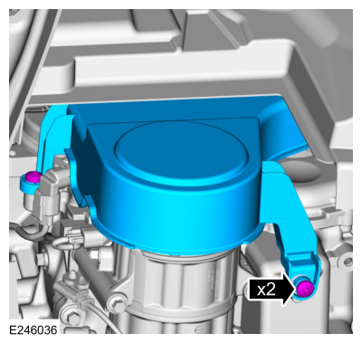
Remove the fasteners and the accessory drive belt cover.
 |
-
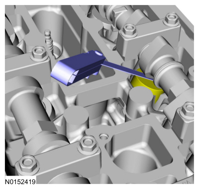
NOTE: Turn the engine clockwise only, and only use the crankshaft bolt.
NOTE: Measure the clearance of each valve at base circle, with the lobe pointed away from the tappet.
Use a feeler gauge to measure the clearance of each valve and record its location.
Use the General Equipment: Feeler Gauge
 |
-
NOTE: The number on the valve tappet only reflects the digits that follow the decimal. For example, a tappet with the number 0.650 has the thickness of 3.650 mm.
NOTE: Select tappets using this formula: tappet thickness = measured clearance + the existing tappet thickness - nominal clearance.
NOTE: The nominal clearance is:
- intake: 0.25 mm (0.0095 in).
- exhaust: 0.36 mm (0.0142 in).
NOTE: The acceptable clearances after being fully installed are:
- intake: 0.19-0.31 mm (0.007-0.012 in).
- exhaust: 0.30-0.42 mm (0.012-0.017 in).
-
If any tappets do not measure within specifications, install new tappets in those locations.
Adjustment
-
NOTE: The following step is only necessary if adjustment is required.
Remove the camshafts.
Refer to: Camshaft (303-01C Engine - 2.0L Duratec-HE (129kW/175PS), Removal and Installation).

 Removal and Installation - Camshaft
Special Tool(s) /
General Equipment
303-1565Alignment Tool, CamshaftTKIT-2010C-FLM
303-507Timing Peg, Crankshaft TDCTKIT-2001N-FLMTKIT-2001N-ROW
Feeler Gauge
Materials
Name
Specification
Flange SealantCU7Z-19B508-A
WSS-M2G348-A11
Removal
NOTICE:
During engine repair procedures, cleanliness is extremely
important..
Other information:
Ford Ecosport 2014-2026 Service and Repair Manual: Removal and Installation - Rear Shock Absorber
Special Tool(s) / General Equipment Transmission Jack Removal NOTICE: Suspension fasteners are critical parts that affect the performance of vital components and systems. Failure of these fasteners may result in major service expense. Use the same or equivalent parts if replacement is necessary. Do not use a replacement part of lesser quality or substitute desi..
Ford Ecosport 2014-2026 Service and Repair Manual: Removal and Installation - Rear Window Wiper Pivot Arm
Special Tool(s) / General Equipment Two Leg Puller Removal NOTICE: Make sure that the motor is in the park position. NOTE: Removal steps in this procedure may contain installation details. Pivot the cover to access the wiper pivot arm nut. Remove the rear widow wiper pivot arm nut. Torque: ..
Categories
- Manuals Home
- 2nd Gen Ford Ecosport Service Manual (2014 - 2026)
- Removal and Installation - Body Control Module (BCM)
- Specifications
- Service Information
- Removal and Installation - Evaporative Emission Canister Purge Valve
- Description and Operation - Jacking and Lifting - Overview
Description and Operation - Health and Safety Precautions
General Service Warnings
Review carefully the information below before beginning any repair. Following these warnings is a list of specific system warnings that must be reviewed before beginning work on any listed system.
 WARNING:
Wear eye and ear protection when servicing a vehicle.
Failure to follow this instruction may result in serious personal
injury.
WARNING:
Wear eye and ear protection when servicing a vehicle.
Failure to follow this instruction may result in serious personal
injury.