
Ford Ecosport: Fuel System - General Information - 2.0L Duratec-HE (129kW/175PS) / General Procedures - Spring Lock Couplings
Ford Ecosport 2014-2026 Service and Repair Manual / Fuel System / Fuel System - General Information - 2.0L Duratec-HE (129kW/175PS) / General Procedures - Spring Lock Couplings
Special Tool(s) / General Equipment
 |
310-250 Disconnect Tool, Fuel Line TKIT-2012A-FL TKIT-2012A-ROW |
Disconnect
NOTICE: When reusing liquid or vapor tube connectors, make sure to use compressed air to remove any foreign material from the connector retaining clip area before separating from the tube or damage to the tube or connector retaining clip can occur. Apply clean engine oil to the end of the tube before inserting the tube into the connector.
NOTICE: Fuel injection equipment is manufactured to very precise tolerances and fine clearances. It is essential that absolute cleanliness is observed when working with these components or component damage can occur. Always install plugs to any open orifices or tubes.
-
If servicing a liquid fuel tube spring lock coupling, release the fuel system pressure.
Refer to: Fuel System Pressure Release (310-00C Fuel System - General Information - 2.0L Duratec-HE (129kW/175PS), General Procedures).
-
Disconnect the battery ground cable.
Refer to: Battery Disconnect and Connect (414-01 Battery, Mounting and Cables, General Procedures).
-
Install the Spring Lock Coupling Disconnect Tool on the
tube and push into the spring lock coupling to release.
Install Suggested Tool: 310-250 Disconnect Tool, Fuel Line. Tool shown or a commercially available equivalent can be used.
 |
-
Separate the spring lock coupling from the tube.
 |
Connect
-
-
Align and push the spring lock coupling onto the tube until fully seated.
-
Pull on the coupling to make sure it is fully engaged.
-
Align and push the spring lock coupling onto the tube until fully seated.
 |
-
Connect the battery ground cable.
Refer to: Battery Disconnect and Connect (414-01 Battery, Mounting and Cables, General Procedures).
 General Procedures - Fuel Tank Draining
Draining
WARNING:
Before beginning any service procedure in this section,
refer to Safety Warnings in section 100-00 General Information...
 General Procedures - Quick Release Coupling
Disconnect
NOTICE:
When reusing liquid or vapor tube connections, make sure to
use compressed air to remove any foreign material from the connector
retaining clip area before separating from the tube or damage to the
tube or connector retaining clip may occur...
Other information:
Ford Ecosport 2014-2026 Service and Repair Manual: General Procedures - Air Conditioning (A/C) Clutch and Air Conditioning (A/C) Clutch Field Coil
Special Tool(s) / General Equipment 412-001 (T71P-19703-B) Remover, Compressor Pulley Activation Remove the A/C compressor. Refer to Air Conditioning A/C Compressor procedure in Group 412. NOTE: If equipped with spring rubber clutch...
Ford Ecosport 2014-2026 Service and Repair Manual: Removal and Installation - Hydraulic Control Unit (HCU)
Removal NOTE: Removal steps in this procedure may contain installation details. NOTE: A new HCU is equipped with a new ABS module. NOTE: The PMI process must begin with the current ABS module installed. If the current ABS module does not respond to the diagnostic scan tool, the tool may prompt for As-Built Data as part of the repair...
Categories
- Manuals Home
- 2nd Gen Ford Ecosport Service Manual (2014 - 2026)
- Removal and Installation - Blower Motor
- Specifications
- Removal and Installation - Evaporative Emission Canister Purge Valve
- Service Information
- Diagnosis and Testing - Evaporative Emissions
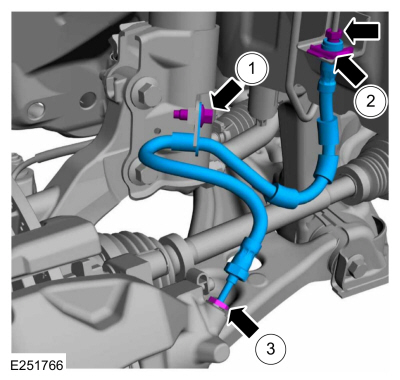
Removal and Installation - Front Brake Flexible Hose
Removal
Remove the wheel and tire.Refer to: Wheel and Tire (204-04A Wheels and Tires, Removal and Installation).
Remove the brake flexible hose bracket bolt.
Disconnect the brake tube fitting and remove the brake hose clip.
Loosen the brake hose fitting and remove the brake flexible hose.

Copyright © 2026 www.foecosport2.com