Ford Ecosport: Front Suspension / Removal and Installation - Lower Arm
Removal
NOTICE: Suspension fasteners are critical parts that affect the performance of vital components and systems. Failure of these fasteners may result in major service expense. Use the same or equivalent parts if replacement is necessary. Do not use a replacement part of lesser quality or substitute design. Tighten fasteners as specified.
-
Remove the wheel and tire.
Refer to: Wheel and Tire (204-04A Wheels and Tires, Removal and Installation).
-
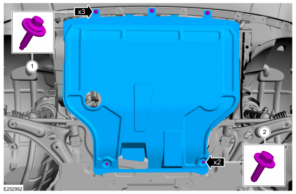
If equipped.
Remove the underbody shield and the retainers.
 |
-
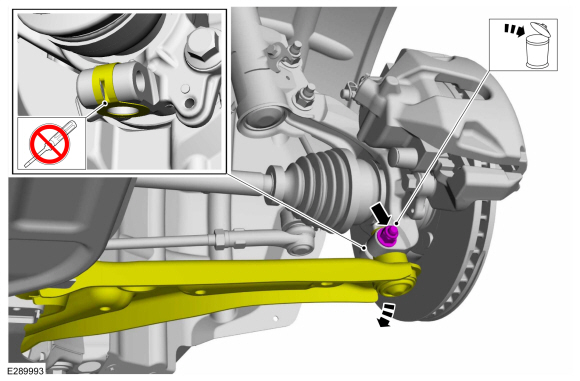
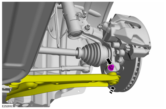
NOTICE: Do not use a prying device to open the slot in the knuckle to separate the lower ball joint from the knuckle assembly. Damage to the knuckle assembly may occur.
NOTICE: Do not use a prying device or separator fork between the ball joint and the wheel knuckle. Damage to the ball joint or ball joint seal may result. Only use the pry bar by inserting it into the lower arm body opening.
NOTICE: Use care when releasing the lower arm and wheel knuckle into the resting position or damage to the ball joint seal may occur.
Remove and discard the lower ball joint pinch bolt and nut and separate the ball joint from the wheel knuckle.
 |
-
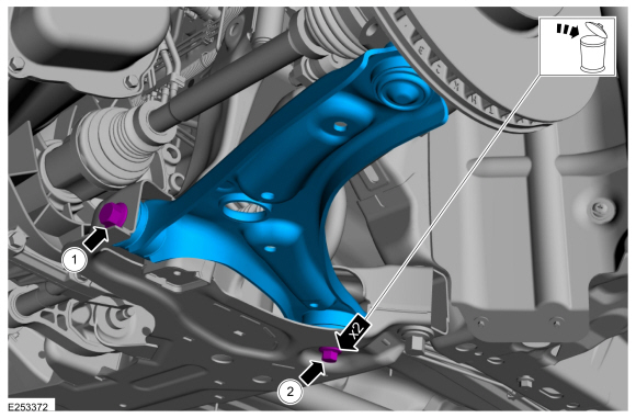
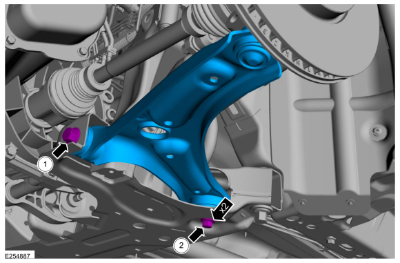
Remove and discard the lower arm forward and rearward bolts and remove the lower arm.
-
Remove and discard the lower arm forward bolt.
-
Remove and discard the lower arm rearward bolt.
-
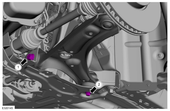
Remove and discard the lower arm forward bolt.
 |
Installation
-
NOTE: Only tighten the bolts finger tight at this stage.
Install the lower arm and new forward and rearward bolts.
-
Install the lower arm new forward bolt.
-
Install the lower arm new rearward bolt.
-
Install the lower arm new forward bolt.
 |
-
On both sides.
Connect the lower ball joint to the wheel knuckle and install the new ball joint pinch bolt and nut.
Torque: 38 lb.ft (52 Nm)
 |
-
Install the wheel and tire.
Refer to: Wheel and Tire (204-04A Wheels and Tires, Removal and Installation).
-
NOTICE: Tighten the suspension bushing fasteners with the suspension loaded or with the weight of the vehicle resting on the wheels and tires, otherwise incorrect clamp load and bushing damage may occur.
Tighten the lower arm forward and rearward bolts.
-
Tighten the front lower arm forward bolt.
Torque:
Stage 1: 76 lb.ft (103 Nm)
Stage 2: 180°
-
Tighten the front lower arm rearward bolt.
Torque:
Stage 1: 46 lb.ft (63 Nm)
Stage 2: 180°
-
Tighten the front lower arm forward bolt.
 |
-
If removed.
Install the underbody shield and the retainers.
Torque:
1: 13 lb.in (1.5 Nm)
2: 22 lb.in (2.5 Nm)
|
-
Check and if necessary adjust front toe.
Refer to: Front Toe Adjustment (204-00 Suspension System - General Information, General Procedures).
 Removal and Installation - Front Stabilizer Bar Bushing
Removal
NOTICE:
Suspension fasteners are critical parts that affect the
performance of vital components and systems. Failure of these fasteners
may result in major service expense...
 Removal and Installation - Wheel Knuckle
Special Tool(s) /
General Equipment
204-161
(T97P-1175-A)
Installer, HalfshaftTKIT-1997-LM2TKIT-1997-F/FM2TKIT-1997-FLM2
205-D070
(D93P-1175-B)
Remover, Front Wheel Hub
Tie Rod End Remover
Removal
NOTICE:
Suspension fasteners are critical parts that affect the
performance of vital components and systems...
Other information:
Ford Ecosport 2014-2026 Service and Repair Manual: Removal and Installation - Transmission Range (TR) Sensor
Special Tool(s) / General Equipment Punch Locking Pliers Removal Remove the main control cover. Refer to: Main Control Cover (307-01B Automatic Transmission - 6-Speed Automatic Transmission – 6F35, Removal and Installation)...
Ford Ecosport 2014-2026 Service and Repair Manual: Removal and Installation - Side Panel
Special Tool(s) / General Equipment Resistance Spotwelding Equipment Spherical Cutter Hot Air Gun Air Body Saw 8 mm Drill Bit MIG/MAG Welding Equipment Spot Weld Drill Bit Locking Pliers Materials Name Specification Metal Bonding AdhesiveTA-1, TA-1-B, 3M™ 08115, LORD Fusor® 108B, Henkel Teroson EP 5055 -&n..
Categories
- Manuals Home
- 2nd Gen Ford Ecosport Service Manual (2014 - 2026)
- Removal and Installation - Catalytic Converter
- General Procedures - Transmission Fluid Level Check
- Specifications
- Removal and Installation - Starter Motor
- Automatic Transmission - 6-Speed Automatic Transmission – 6F35
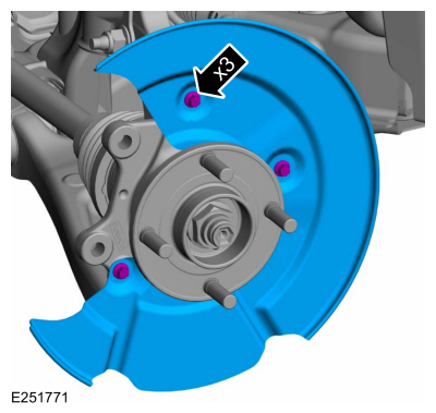
Removal and Installation - Brake Disc Shield
Removal
NOTE: Removal steps in this procedure may contain installation details.
Remove the brake disc.Refer to: Brake Disc (206-03 Front Disc Brake, Removal and Installation).
Remove the bolts and brake disc.
Torque: 80 lb.in (9 Nm)