Ford Ecosport: Automatic Transmission - 6-Speed Automatic Transmission – 6F35 / Description and Operation - Transmission Fluid Auxiliary Pump
Ford Ecosport 2014-2026 Service and Repair Manual / Automatic Transmission / Automatic Transmission - 6-Speed Automatic Transmission – 6F35 / Description and Operation - Transmission Fluid Auxiliary Pump
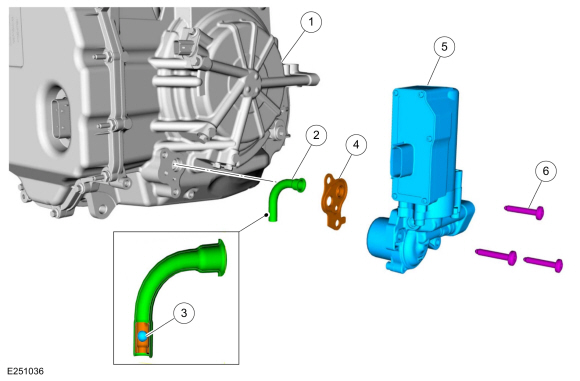
Transmission Fluid Auxiliary Pump Components
| Item | Description |
| 1 | Transmission assembly |
| 2 | Transmission fluid auxiliary pump supply tube assembly |
| 3 | Check ball (part of the transmission fluid auxiliary pump supply tube) |
| 4 | Transmission fluid auxiliary pump-to-transmission case gasket |
| 5 | Transmission fluid auxiliary pump |
| 6 | Transmission fluid auxiliary pump-to-transmission case bolt (3 required) |
Mechanical Operation
The transmission fluid auxiliary pump is an electric external pump bolted to the transmission case that draws fluid from the sump area of the transmission through the pump supply tube. The transmission fluid auxiliary pump maintains line pressure during engine shut down on vehicles equipped with the Auto-Start-Stop System. The transmission auxiliary fluid pump is controlled by the PCM .

 Diagnosis and Testing - Diagnostic Strategy
Overview
The
diagnostic process for each transmission concern will vary depending on
the symptoms and condition of the vehicle. The diagnostic process
below is an efficient method to collect as much data as possible about
the concern before performing a repair or removing the transmission from
the vehicle for teardown and further inspection...
Other information:
Ford Ecosport 2014-2026 Service and Repair Manual: Description and Operation - Overdrive Clutch Assembly
Overdrive (O/D) (4, 5, 6) Clutch Exploded View Item Description 1 Direct/overdrive clutch hub assembly 2 Overdrive clutch piston inner seal 3 Input shaft 4 Overdrive clutch piston outer seals 5 Overdrive clutch piston ..
Ford Ecosport 2014-2026 Service and Repair Manual: General Procedures - Cylinder Bore Taper
Check NOTE: Refer to the appropriate Section 303-01 for the specification. Measure the cylinder bore at the top, middle and bottom of piston ring travel in 2 directions as indicated. Verify the cylinder bore is within the wear limit. The difference indicates the cylinder bore taper. If the cylinder bore taper does not meet specification, bore the cylinder to the next ..
Categories
- Manuals Home
- 2nd Gen Ford Ecosport Service Manual (2014 - 2026)
- Description and Operation - Evaporative Emissions - System Operation and Component Description
- Removal and Installation - Evaporative Emission Canister Purge Valve
- Removal and Installation - Roof Rail
- Description and Operation - Jacking and Lifting - Overview
- Diagnosis and Testing - Evaporative Emissions
Removal and Installation - Variable Camshaft Timing (VCT) Unit
Removal
NOTICE: During engine repair procedures, cleanliness is extremely important. Any foreign material, including any material created while cleaning gasket surfaces, that enters the oil passages, coolant passages or the oil pan can cause engine failure.
Remove the timing chain.Refer to: Timing Chain (303-01C Engine - 2.0L Duratec-HE (129kW/175PS), Removal and Installation).
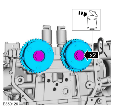
Remove the bolts and VCT units.
Discard the bolts.
Copyright © 2026 www.foecosport2.com