Ford Ecosport: Automatic Transmission - 6-Speed Automatic Transmission – 6F35 / Description and Operation - Differential
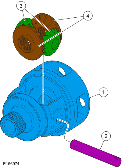
Differential Exploded View
| Item | Description |
| 1 | Differential housing |
| 2 | Pinion shaft |
| 3 | Pinion gears |
| 4 | Side gears |
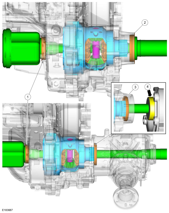
Differential Cutaway View and External Sealing
| Item | Description |
| 1 | LH halfshaft seal |
| 2 | RH halfshaft seal FWD (front wheel drive) |
| 3 | RH halfshaft seal AWD (All-wheel drive) |
| 4 | Power Transfer Unit (PTU) input shaft sealing surface |
Differential
The differential allows the halfshafts and wheels to rotate at different speeds during cornering and transfers power to the Power Transfer Unit (PTU) for AWD vehicles.
The differential assembly consists of the following components:
- Differential case (part of the final drive carrier)
- Two pinion gears supported by a pinion shaft
- Two side gears supported by the differential case and halfshafts
When driving in a straight line, both front wheels rotate at relatively the same speed. This means both side gears are rotating at the same speed, as well, while both pinion gears revolve (but do not rotate) with the side gears. During cornering, the wheel on the outside of the turn is forced to rotate faster than the wheel on the inside of the turn. Since the side gears must now rotate at different speeds, the pinion gears rotate on the pinion shaft allowing the drive axles to rotate at different speeds while still transferring output torque.

 Description and Operation - Transmission Fluid Auxiliary Pump
Transmission Fluid Auxiliary Pump Components
Item
Description
1
Transmission assembly
2
Transmission fluid auxiliary pump supply tube assembly
3
Check ball (part of the transmission fluid auxiliary pump supply tube)
4
Transmission fluid auxiliary..
Other information:
Ford Ecosport 2014-2026 Service and Repair Manual: General Procedures - Refrigerant System Tests - 2.0L Duratec-HE (129kW/175PS)
Inspection NOTE: Procedure 1 — Ambient Temperature between 21°C (70°F) and 38°C (100°F) NOTE: Variable compressors may not stroke up unless the ambient temperatures are above 21°C (70°F) when conducting the pressure mapping procedure. Variable compressor need to see a thermal load on the system in order to create normal operating pressures. Run the engine ..
Ford Ecosport 2014-2026 Service and Repair Manual: Removal and Installation - Quarter Panel LH
Special Tool(s) / General Equipment Resistance Spotwelding Equipment Spherical Cutter Grinder Air Body Saw 8 mm Drill Bit MIG/MAG Welding Equipment Spot Weld Drill Bit Locking Pliers Materials Name Specification Metal Bonding AdhesiveTA-1, TA-1-B, 3M™ 08115, LORD Fusor® 108B, Henkel Teroson EP 5055 - ..
Categories
- Manuals Home
- 2nd Gen Ford Ecosport Service Manual (2014 - 2026)
- Description and Operation - Evaporative Emissions - System Operation and Component Description
- Body and Paint
- Removal and Installation - Front Seat
- General Procedures - Transmission Fluid Level Check
- Removal and Installation - Catalytic Converter
Removal and Installation - Steering Column Shaft
Removal
NOTE: Removal steps in this procedure may contain installation details.
NOTICE: Do not allow the steering column to rotate while the steering column shaft is disconnected or damage to the steering column internal sensor may result.
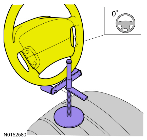
NOTE: Use a steering wheel holding device (such as Hunter® 28-75-1 or equivalent)
Hold the steering wheel in the straight-ahead position.