Ford Ecosport: Engine - 2.0L Duratec-HE (129kW/175PS) / Disassembly and Assembly of Subassemblies - Piston
Ford Ecosport 2014-2026 Service and Repair Manual / Engine / Engine - 2.0L Duratec-HE (129kW/175PS) / Disassembly and Assembly of Subassemblies - Piston
DISASSEMBLY
-
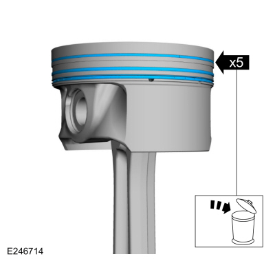
Remove the piston rings and discard.
 |
-
-
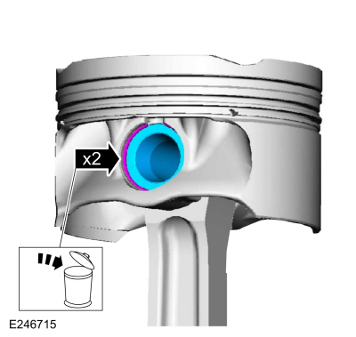
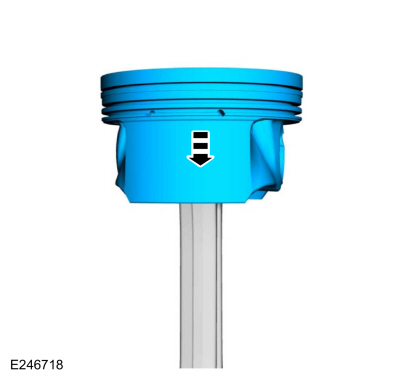
Remove the piston pin retainers and discard.
-
Remove the piston pin.
-
Remove the piston pin retainers and discard.
 |
-
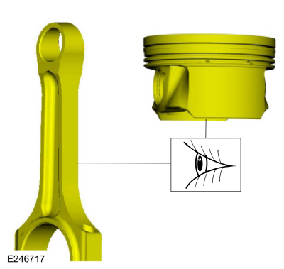
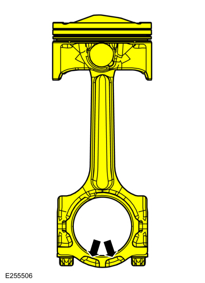
Remove the piston from the connecting rod.
 |
-
Inspect the piston.
Refer to: Piston Inspection (303-00 Engine System - General Information, General Procedures).
 |
ASSEMBLY
-
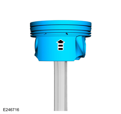
Indicates front of engine.
 |
-
Install the piston to the connecting rod.
 |
-
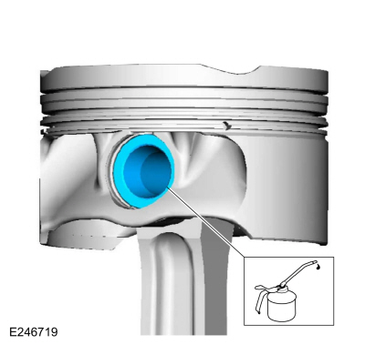
Lubricate with clean engine oil and install the piston pin.
 |
-
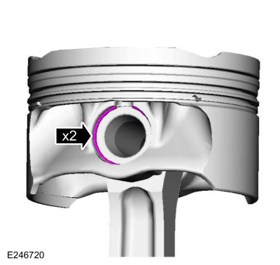
Install the piston pin retainers.
 |
-
Lubricate with clean engine oil and install the piston rings.
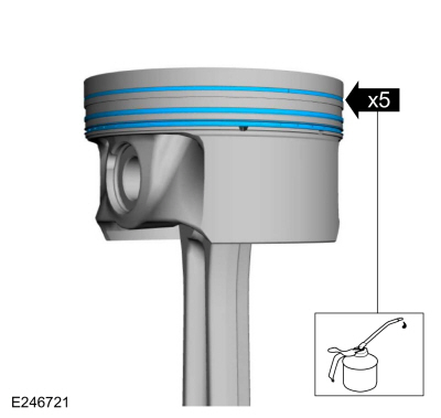 |
-
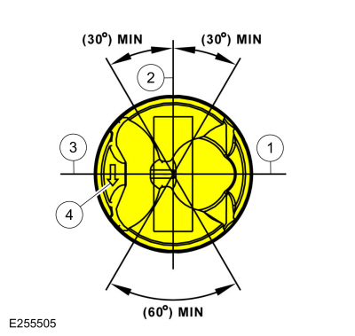
NOTE: Align the piston rings on the piston.
-
Upper oil control segment ring gap location.
-
Oil control spacer gap location.
-
Lower oil control segment ring gap location.
-
Piston to be assembled with the arrow pointing to the front of the engine.
-
Upper oil control segment ring gap location.
 |

 Assembly - Engine
Special Tool(s) /
General Equipment
100-002
(TOOL-4201-C)
Holding Fixture with Dial Indicator Gauge
205-153
(T80T-4000-W)
Handle
303-096
(T74P-6150-A)
Installer, Camshaft Front Oil SealTKIT-2009TC-F
303-103
(T74P-6375-A)
Holding Tool, FlywheelT74P-77000-ATKIT-2009TC-F
303-1247VCT Spark Plug Tube Seal Remover and InstallerTKIT-..
Other information:
Ford Ecosport 2014-2026 Service and Repair Manual: Diagnosis and Testing - Pinpoint Test - DTC: AJ, Vehicles With: Rear Seat Side Airbag
U0413:56 Normal Operation and Fault Conditions The RCM uses information contained in messages from the BECMB sent on the HS-CAN2 . DTC Fault Trigger Conditions DTC Description Fault Trigger Conditions U0413:56 Lost Communication with Body Control Module: No Sub Type Informat..
Ford Ecosport 2014-2026 Service and Repair Manual: General Procedures - Body Panel Sectioning
Special Tool(s) / General Equipment Resistance Spotwelding Equipment Plasma Cutter Air Body Saw MIG/MAG Welding Equipment Spot Weld Drill Bit Materials Name Specification Seam SealerTA-2-B, 3M™ 08308, LORD Fusor® 803DTM - Repair NOTICE: Do not begin removal of the vehicle body side until the replacement pa..
Categories
- Manuals Home
- 2nd Gen Ford Ecosport Service Manual (2014 - 2026)
- General Procedures - Transmission Fluid Level Check
- Service Information
- Removal and Installation - Front Seat
- Body and Paint
- Removal and Installation - Catalytic Converter
Description and Operation - Health and Safety Precautions
General Service Warnings
Review carefully the information below before beginning any repair. Following these warnings is a list of specific system warnings that must be reviewed before beginning work on any listed system.
 WARNING:
Wear eye and ear protection when servicing a vehicle.
Failure to follow this instruction may result in serious personal
injury.
WARNING:
Wear eye and ear protection when servicing a vehicle.
Failure to follow this instruction may result in serious personal
injury.
Copyright © 2026 www.foecosport2.com