Ford Ecosport: Instrumentation, Message Center and Warning Chimes / Description and Operation - Instrument Panel Cluster (IPC) - System Operation and Component Description
System Operation
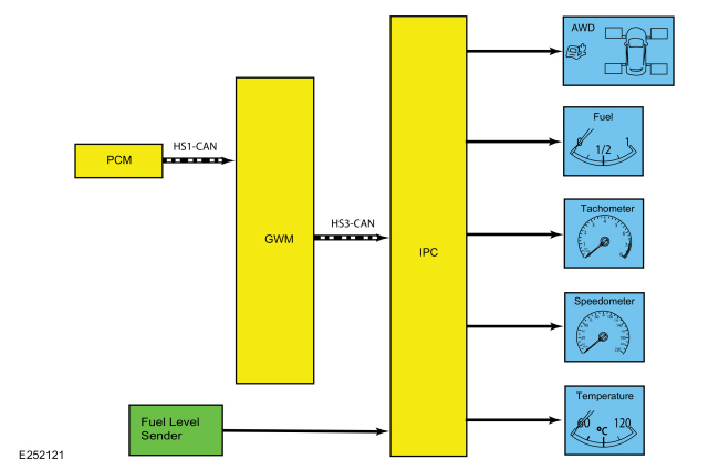
System Diagram - Gauges
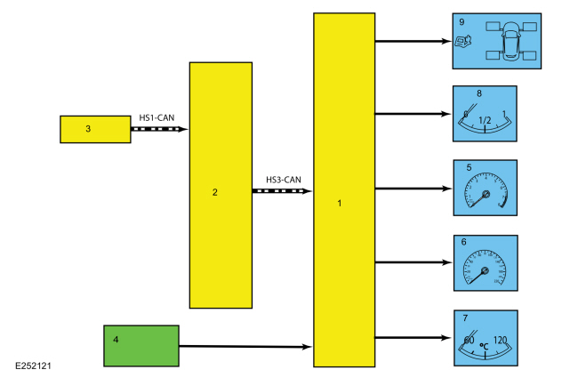
| Item | Description |
|---|---|
| 1 | IPC |
| 2 | GWM |
| 3 | PCM |
| 4 | Fuel level sender |
| 5 | Tachometer |
| 6 | Speedometer |
| 7 | Temperature |
| 8 | Fuel |
| 9 | AWD |
Network Message Chart - Gauges
Module Network Input Messages - IPC
| Broadcast Message | Originating Module | Message Purpose |
|---|---|---|
| AWD service required | PCM | Input used for the AWD gauge display. |
| Engine coolant temperature | PCM | Engine temperature data used for temperature gauge indication. |
| Engine overheat indication request | PCM | Engine temperature data used for temperature gauge indication. |
| Engine rpm data | PCM |
|
| LH front wheel fill percent | PCM | Input used for the AWD gauge display. |
| LH rear wheel fill percent | PCM | Input used for the AWD gauge display. |
| RH front wheel fill percent | PCM | Input used for the AWD gauge display. |
| RH rear wheel fill percent | PCM | Input used for the AWD gauge display. |
| Vehicle speed | PCM |
|
System Diagram - Indicators
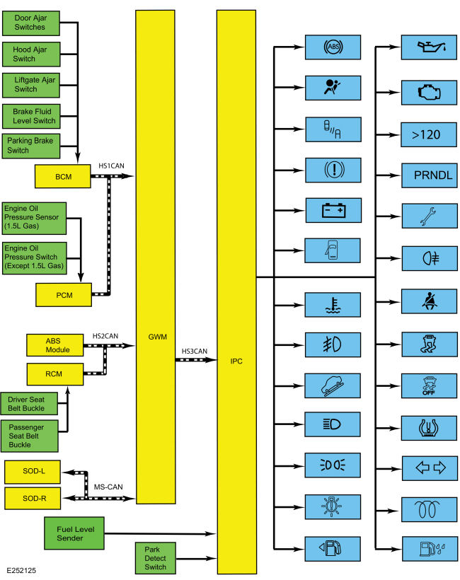
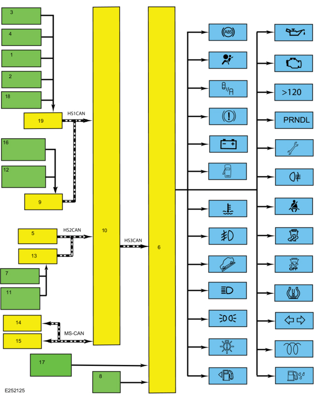
| Item | Description |
|---|---|
| 1 | Liftgate ajar switch |
| 2 | Brake fluid level switch |
| 3 | Door ajar switches |
| 4 | Hood ajar switch |
| 5 | ABS module |
| 6 | IPC |
| 7 | Driver seatbelt buckle |
| 8 | Park detect switch |
| 9 | PCM |
| 10 | GWM |
| 11 | Passenger seatbelt buckle |
| 12 | Engine oil pressure switch (except 1.5L gas) |
| 13 | RCM |
| 14 | SODL |
| 15 | SODR |
| 16 | Engine oil pressure sensor (1.5L gas) |
| 17 | Fuel Level Sender |
| 18 | Parking brake switch |
| 19 | BCM |
Network Message Chart - Indicators
Module Network Input Messages - IPC
| Broadcast Message | Originating Module | Message Purpose |
|---|---|---|
| ABS warning indicator request | ABS module | Input used to control the ABS warning indicator. |
| AWD service required request | PCM | Input used to control the powertrain malfunction (wrench) indicator for the AWD system input. |
| Airbag indicator request | RCM | Input used to control the airbag warning indicator. |
| Battery low state of charge | BCM | Input used to control the charging system warning indicator. |
| Body service required request | BCM | Input used to control the powertrain malfunction (wrench) indicator for the BCM input. |
| Brake warning indicator request | BCM | Input used to control the brake warning indicator for the parking brake and brake fluid level inputs. |
| Brake (red) warning indicator request | ABS module | Input used to control the brake warning indicator for an ABS fault input. |
| Driver door ajar status | BCM | Input used to control the door ajar warning indicator. |
| Driver seatbelt buckle status | RCM | Input used to control the seatbelt warning indicator. |
| Engine coolant temperature | PCM | Input used to control the engine over-temperature warning indicator. |
| Engine rpm data | PCM | Input used to control the low oil pressure warning indicator. |
| Engine overheat indication request | PCM | Input used to control the engine over-temperature warning indicator. |
| Engine service required request | PCM | Input used to control the powertrain malfunction (wrench) indicator for the Electronic Throttle Control (ETC) input. |
| Front fog lamp indicator request | BCM | Input used to control the front fog lamp indicator. |
| Glow indication | PCM | Input used to control the wait to start indicator (diesel and E100 only). |
| Headlamp high/low status | BCM | Input used to control the high beam indicator. |
| Headlamp low beam out | BCM | Input used to control the low beam malfunction indicator. |
| Hood ajar status | BCM | Input used to control the door ajar warning indicator. |
| Ignition status | BCM |
|
| Left rear door ajar status | BCM | Input used to control the door ajar warning indicator. |
| Left turn lamp on request | BCM | Input used to control the LH turn or hazard indicators. |
| Liftage ajar status | BCM | Input used to control the door ajar warning indicator. |
| MIL request | PCM | Input used to control the MIL . |
| Oil pressure warning indicator request | PCM | Input used to control the low oil pressure warning indicator. |
| Park lamp status | BCM | Input used to control the lights on (side marker positon) indicator. |
| Passenger door ajar status | BCM | Input used to control the door ajar warning indicator. |
| Power shed level request | BCM | Input used to control the PRNDL display. |
| Powertrain drive mode | PCM | Input used to control the grade assist indicator (if equipped). |
| Rear fog lamp indicator request | BCM | Input used to control the rear fog lamp indicator (if equipped). |
| Right rear door ajar status | BCM | Input used to control the door ajar warning indicator. |
| Right turn indicator status | BCM | Input used to control the RH turn or hazard indicators. |
| Side obstacle detect status - left | SODL | Input used to control the BLIS indicator. |
| Side obstacle detect status - right | SODR | Input used to control the BLIS indicator. |
| Stability-traction control indication | ABS module | Input used to control the stability-traction control indicator (sliding car icon). |
| Stop/start standy indicator | PCM | Input usd to control the stop-start indicator (if equipped). |
| Tire pressure warning indication | BCM | Input used to control the TPMS indicator |
| Traction control mode | ABS module | Input used to control the stability-traction control disabled indicator (sliding car OFF icon). |
| Transmission gear display mode | PCM | Input used to control the PRNDL display on, off or flash. |
| Transmission gear display | PCM | Input used to control the selected gear displayed (including the manual SelectShift selections) in the PRNDL. |
| Transmission service required request | PCM | Input used to control the powertrain malfunction (wrench) indicator for the transmission input. |
| Transport mode | BCM | Input used to control the PRNDL display at ignition off. |
| Vehicle speed | PCM | Input used to control the overspeed warning indicator (Gulf Coast Countries [GCC] only). |
| Water in fuel indicator | PCM | Input used to control the water in fuel indicator (diesel only). |
Module Network Input Messages - SODL and SODR
| Broadcast Message | Originating Module | Message Purpose |
|---|---|---|
| BLIS enable status | IPC | Input used to control the BLIS based on driver enable-disable input. |
Configuration
The IPC
contains items that are configurable. Configurable items include
customer preference items, which can also be set with a scan tool. The
remaining configurable items can only be set through the vehicle
configuration parameters.
Refer to: Module Configuration - System
Operation and Component Description (418-01 Module Configuration,
Description and Operation).
Dealer Test Mode
To enter the IPC dealer test mode, begin with the ignition in OFF. Press and hold the LH steering wheel switch OK button. Place the ignition in ON and hold the button until the display indicates Test or Gauge Sweep, usually within 3-5 seconds. Press the up or down arrow buttons to navigate through each of the display windows. To exit the IPC dealer test mode, press and hold the OK button for 5 seconds or place the ignition in OFF. Each button press advances the viewing window to the next set of items.
MyKey®
The MyKey® feature allows the customer to program a restricted driving mode that is tied to one or more keys known as a MyKey® key. The following features are provided by the IPC when a MyKey® key is being used:
- At the beginning of vehicle start up, as part of the welcome strategy, the message center greets the MyKey® driver with MYKEY ACTIVE DRIVE SAFELY displayed in the message center. If the MyKey® speed limiter feature is turned on, the message center also displays the MyKey® administrator selected top speed setting message; SPEED LIMITED TO XX MPH (km/h). The MyKey® top speed selections are; 100, 110, 120 or 130 kmh (62, 68, 75, or 81 mph) or to the administrator desired setpoint.
- The IPC provides a periodic Belt-Minder® warning chime until the driver and passenger safety belts are buckled. When the Belt-Minder® is issued, the ACM is muted and the message center displays BUCKLE UP TO UNMUTE AUDIO.
- If the MyKey® speed limiter feature is turned on and the vehicle speed approaches the selected top speed (100, 110, 120 or 130 kmh [62, 68, 75, or 81 mph]), the message center displays NEAR VEHICLE TOP SPEED along with a chime.
- If the MyKey® speed limiter feature is turned on and the vehicle speed reaches the selected top speed (100, 110, 120 or 130 kmh [62, 68, 75, or 81 mph]), the message center displays VEHICLE AT TOP SPEED OF MYKEY SETTING along with a chime.
- If the speed warning is selected at one of the preset values (75, 90, 100 km/h [47, 58, 62 mph]) and the vehicle approaches the preset speed, the message center displays CHECK SPEED DRIVE SAFELY along with a chime.
- At approximately 1/8 tank of remaining fuel, the IPC illuminates the low fuel message center indicator and the message center displays FUEL LEVEL LOW along with a chime.
- Traction control emergency assistance or emergency 911 Assist® feature (except Mexico), the Do Not Disturb feature and the Lane Departure Alert can be set to always on or user selectable in the MyKey® menu.
- If the traction control always on feature is turned on and the MyKey® driver attempts to disable the traction control, the message center displays ADVANCETRAC ON MYKEY SETTING.
- MyKey® miles driven by the MyKey® user can be found in the information display.
- The number of MyKey® programmed and administrator keys can be found in the MyKey® menu.
- The parking aid, BLIS / CTA and collision avoidance warning menus are disabled in the message center to force these features always on.
When an administrator key is in use, the IPC provides:
- a menu in the message center guiding the user to create a MyKey®. When the maximum MyKey® limit is reached, the MyKey® creation menu is no longer available.
-
a menu in the message center with options for setting 6 optional MyKey® features:
- MyKey® speed limiter
- MyKey® pre-selected speed warning
- MyKey® radio volume limiter
- traction control always on or user selectable
- emergency 911 assist feature always on or user selectable
- do not disturb feature always on or user selectable
- a menu to clear all MyKey® programmed keys at once.
- MyKey® mileage driven by the MyKey® user in system check function of the message center.
- the number of MyKey® programmed keys and administrator keys in the system check function of the message center.
For information on the MyKey® features, refer to the Owner's Literature.
Hardwired Inputs
The IPC requires hardwired inputs from components that are not on the CAN . These components are required for specific IPC functions.
The hardwired inputs are provided by the following components:
- Fuel level sender (float and card)
- Park detect switch
- Low washer fluid level switch (Russia only)
Networked Input Messages and Default States
NOTE: Whenever a network message is suspected as missing and confirmed by a missing message DTC (U-code), it is important to look for other symptoms that can also be present in the IPC and throughout the vehicle. Once a DTC sets in the IPC , it is helpful to review the complete message list to determine which other modules also rely on the same message and run the self-test for those modules. If the message is missing from other modules, the same or similar lost communication DTC can also be set in those modules. Confirmation of missing messages common to multiple modules can indicate the originating module is the source of the concern or the communication network may be faulted.
For a list of all the network messages,
Refer to: Communications
Network - System Operation and Component Description (418-00 Module
Communications Network, Description and Operation).
The IPC uses input messages from other modules to control the gauges, informational indicators, warning indicators and message center message displays over the communication networks. The IPC receives all networked data over the HS-CAN3 .
The vehicle uses 4 communication networks to transmit the data used by the IPC .
- HS-CAN1
- HS-CAN2
- HS-CAN3
- MS-CAN
For overview information,
Refer to: Communications Network - Overview (418-00 Module Communications Network, Description and Operation).
For system operation information,
Refer to: Communications
Network - System Operation and Component Description (418-00 Module
Communications Network, Description and Operation).
All messaged inputs to the IPC from other networks are received from the GWM over the HS-CAN3 . The GWM , as the name implies, acts as a gateway to convert messages from one of the other 3 networks to the HS-CAN3 , which is recognized by the IPC .
Network messages can drop out or be missing for a variety of reasons, such as high network traffic on the bus. The IPC incorporates a defined strategy for handling missing network messages based on time. The required time for a network message to be missing differs between the various gauges, indicators and message center displays. The strategy is basically the same for all indication outputs (gauges, indicators or chimes), but differs in the length of time required for the network message to be missing. If a required network message is missing or invalid for less than the programmed length of time, the gauge, indicator or message center display that requires the network message remains at the last commanded state based upon the last network message received. If the messaged input is missing for longer than the programmed length of time, the IPC output (gauge, indicator etc.) reacts according to a pre-defined default action.
For example, if the stability-traction control indicator request network message is missing for less than 5 seconds, and the stability-traction control indicator (sliding car icon) was on, the indicator remains in the on state until the next network message is received. If the network message remains missing or invalid for more than 5 seconds, the IPC sets a U-code DTC and the IPC output becomes a default action for the indicator or gauge. The indicator may default on/off or the gauge may default to the rest position.
Each indicator or gauge utilizes a different default strategy depending on the nature of the indication. Refer to the diagnostic overview descriptions located before each pinpoint test for further descriptions of the default action specific to each indicator or gauge. If the missing messaged input to the IPC returns at any time, the normal function of the gauge, indicator or message center display resumes.
It is very important to understand:
- where the input originates.
- all the information necessary in order for a feature to operate.
- which module(s) receive(s) the input or command message.
- which module controls the output of the feature.
- whether the module that receives the input controls the output of the feature, or whether it outputs a message over the communication network to another module.
Prove-Out
The IPC and other modules carry out a display prove-out to verify all module controlled warning/indicator lamps and monitored systems are functioning correctly within the IPC . The IPC and other modules, such as the RCM , provide a timed prove-out of some indicators while other indicators illuminate upon engine start up. When the ignition is cycled to on with the engine off, the indicators illuminate to prove-out according to the following table:
| Indicator | Indicator Type | Prove-Out Duration |
|---|---|---|
| ABS | Warning | 3 seconds |
| Airbag | Warning | 8 seconds |
| Auto stop-start (if equipped) | Informational | None |
| BLIS | Informational | 3 seconds |
| Brake | Warning | 3 seconds |
| Charge | Warning | Engine startup |
| Door ajar | Informational | 3 seconds or when all open doors are closed after the initial 3 second proveout |
| Engine over-temperature | Warning | 3 seconds |
| Front fog lamp | Informational | None |
| Grade assist (if equipped) | Informational | None |
| High beam | Informational | None |
| Lights on (side marker position) | Informational | None |
| Low fuel | Informational | 3 seconds |
| Low oil pressure | Warning | Engine startup |
| MIL | Warning | Engine startup |
| Overspeed warning | Warning | None |
| Powertrain malfunction (wrench) indicator | Informational | 3 seconds |
| Rear fog lamp (if equipped) | Informational | None |
| Seatbelt | Warning |
|
| Stability-traction control (sliding car icon) | Warning | 3 seconds |
| Stability-traction control disabled (sliding car OFF icon) | Informational | 3 seconds |
| TPMS | Warning | 3 seconds |
| RH / LH turn | Informational | None |
| Wait to start (diesel and E100 engines only) | Informational | None |
| Water in fuel (diesel only) | Informational | 3 seconds |
Startup-Shutdown
The IPC provides a startup-shutdown sequence also known as a welcome-farewell strategy. When the BCM receives a RKE request or door ajar (open) input, the IPC illuminates the RH and LH turn indicators briefly then displays the message center splash screen. When the ignition is placed in the RUN or START mode, the message center proves out and defaults to normal operation. The IPC illuminates all LED indicators for a predetermined time (prove-out).
Factory - Transport Mode
During vehicle build, some vehicle modules (IPC , ACM , APIM and BCM
) are set in factory mode. While in the factory mode the IPC
displays FACTORY MODE CONTACT DEALER in the message center. If the
vehicle is set in factory mode, the system does not automatically exit
the mode and must be manually set to either the transport or normal
operation mode. When the vehicle build is complete, the vehicle is set
to transport mode. While in transport mode, the IPC
displays TRANSPORT MODE CONTACT DEALER in the message center.
Transport mode is used to reduce the drain on the battery during longer
periods where the vehicle is not used. Various systems may be altered or
are disabled when in the transport mode. The vehicle automatically
reverts to normal operation mode after being driven 201 km (125 mi). To
disable or turn off the factory mode,
Refer to: Factory Mode Deactivation (419-10 Multifunction Electronic Modules, General Procedures).
To disable the transport mode, Refer to: Transport Mode Deactivation
(419-10 Multifunction Electronic Modules, General Procedures).
Gauges
AWD Gauge
The AWD gauge is a virtual gauge that displays the level of power applied to front and rear wheels. The IPC uses the following inputs to determine the AWD gauge display:
- AWD service required
- LH front wheel fill percent
- LH rear wheel fill percent
- RH front wheel fill percent
- RH rear wheel fill percent
As power is applied to the wheels, the area directly to the side of each displayed wheel begins to fill in. The lowest power displayed is the closest to the front of the fill area. As the amount of power sent to the wheels increases, the area next to the wheel fills rearward. Both front wheels fill equally for increased front wheel power and when power is applied to the rear wheels, the area next to the rear wheels fill in equally.
The IPC receives all required messages from the GWM over the HS-CAN3 . The GWM receives all required messages from the PCM over the HS-CAN1 .
Fuel Gauge
The IPC sends a reference voltage to the fuel level sender. As the fuel level changes, a float actuates the variable resistor fuel level sender, raising or lowering the fuel level signal voltage. The IPC monitors the changes in voltage from the fuel level sender and commands the fuel gauge with a corresponding movement of the pointer.
After a fuel fill up, the time for the fuel gauge to move from empty (E) to full (F) ranges from 2 seconds to 55 minutes depending on which operating mode the fuel gauge is in.
The IPC uses 4 different operating modes to calculate the fuel level:
- Anti-slosh (default mode)
- Key OFF fueling
- Key ON fueling
- Recovery
The default fuel gauge mode is called the anti-slosh mode. To prevent fuel gauge changes from fuel slosh (gauge instability due to changes in fuel sensor readings caused by fuel moving around in the tank), the fuel gauge takes approximately 40 minutes to go from empty (E) to full (F).
The key OFF fueling mode (2 seconds to read empty [E] to full [F]) requires 3 conditions to be met:
- The ignition must be in the OFF mode when refueling the vehicle.
- At least 6% of the vehicle's fuel capacity must be added to the fuel tank.
- The IPC must receive a valid ignition ON fuel sensor reading within one second of the ignition being put into the RUN mode. The key ON sample readings are considered valid if the fuel sensor reading is between 10 ohms ± 2 ohms and 180 ohms ± 4 ohms.
If these conditions are not met, the fuel gauge stays in the anti-slosh mode, which results in a slow to read full (F) event.
The key ON fueling mode (approximately 60 seconds to read empty [E] to full [F]) requires the following conditions be met:
- The transmission is in PARK (P) or NEUTRAL (N).
- The ignition is in the RUN mode.
- At least 6% of the vehicle's fuel capacity must be added to the fuel tank
In key ON fueling mode, a 30-second timer activates after the transmission is put into the PARK (P) or NEUTRAL (N) position. When the 30-second time has elapsed and at least 9% of the vehicle's fuel capacity has been added, the fuel gauge response time is 60 seconds to read from empty (E) to full (F). When the transmission is shifted out of PARK (P) or NEUTRAL (N), the fuel gauge strategy reverts to the anti-slosh mode. The key ON fueling mode prevents slow to read full events from happening if the customer refuels the vehicle with the ignition in the RUN mode.
Recovery mode is incorporated into the IPC strategy to recover from a missing fuel level input after a refueling event. Missing fuel level inputs result from intermittent opens in the fuel sensor or its circuits. Recovery mode (empty [E] to full [F] approximately 17 minutes) is initiated when the following 2 conditions are met:
- The IPC is in the anti-slosh (default) mode.
- The actual fuel level in the tank is 5% different from what is being displayed by the fuel gauge.
Speedometer
The IPC receives the vehicle speed data from the GWM over the HS-CAN3 . The GWM receives the vehicle speed message from the PCM over the HS-CAN1 .
The PCM receives the wheel speed data through the GWM over the HS-CAN1 . The GWM receives the wheel speed data from the ABS module over the HS-CAN2 .
The PCM uses tire size stored in the vehicle configuration file along with wheel speed inputs to generate a vehicle speed signal.
For North America, the IPC provides a tolerance that allows the speed indication to display between 3% below and 7% above the actual vehicle speed. This means that with an actual vehicle speed of 97 km/h (60 mph), the speedometer can indicate between 94-103 km/h (58-64 mph). Incorrect tire size or tire size configuration could potentially affect the speedometer accuracy.
For markets except North America, the IPC provides a tolerance that allows the speed indication to display between 0% below and 10% above the actual vehicle speed. This means that with an actual vehicle speed of 100 km/h (62 mph), the speedometer can indicate between 100-110 km/h (62-68 mph). Incorrect tire size or tire size configuration could potentially affect the speedometer accuracy.
Tachometer
The IPC receives the engine rpm data message from the GWM over the HS-CAN3 . The GWM receives the engine rpm data message from the PCM over the HS-CAN1 .
Temperature Gauge
The IPC uses 2 messages to control the temperature gauge. The first is the engine coolant temperature, which provides the current engine temperature input to the PCM . The second message is the engine overheat indication request, which is sent by the PCM to the IPC when an overheating condition exists. When the IPC receives the engine overheat indication request message, the IPC sends the temperature gauge to full hot and turns on the over-temperature warning indicator.
The IPC receives both temperature gauge input messages from the GWM over the HS-CAN3 . The GWM receives the engine coolant temperature and the engine overheat indication request messages from the PCM over the HS-CAN1 .
Indicators
ABS
The IPC receives the ABS warning indicator request message from the GWM over the HS-CAN3 . The GWM receives the ABS warning indicator request message from the ABS module over the HS-CAN2 . If a fault condition exists in the ABS , the ABS module sends the ABS warning indicator request message to either flash or illuminate the ABS warning indicator.
Refer to ABS /Brake/Stability-Traction Control System Indication description for information on the conditions when the ABS indicator is turned on.
Airbag Warning
The IPC receives the airbag warning indicator request from the GWM over the HS-CAN3 . The GWM receives the airbag indicator request from the RCM over the HS-CAN2 . If a SRS concern is detected, the RCM sets a DTC and the IPC illuminates the airbag warning indicator.
Auto Stop-Start (If Equipped)
The IPC provides the auto stop-start indicator to inform the driver of the status of the engine status. The IPC receives the stop/start standby request from the GWM over the HS-CAN3 . The GWM receives the auto stop/start standby request from the PCM over the HS-CAN1 .
BLIS
When the BLIS is turned off by the driver or disabled by the BLIS , the IPC turns on the BLIS indicator.
The IPC provides the BLIS / CTA enable request message to the SODL and SODR over the MS-CAN to enable or disable the BLIS based on driver input through the message center controls. The IPC receives the side obstacle detect status-left and side obstacle detect status-right messages from the SODL and SODR over the MS-CAN .
Brake Warning
The brake warning indicator informs the driver the brake fluid level is low, there is a failure in the base brake system or the park brake is applied. The IPC uses 2 messaged inputs to control the brake warning indicator.
- Brake (red) warning indicator request
- Brake warning indicator request (used for both low brake fluid level and parking brake applied states)
The IPC receives both the brake (red) warning indicator request and the brake warning indicator request messages from the GWM over the HS-CAN3 .
The GWM receives the brake (red) warning indicator request from the ABS module over the HS-CAN2 .
The GWM receives the brake warning indicator request message request from the BCM over the HS-CAN1 .
Charging System Warning
The charging system warning indicator informs the driver that a fault is detected in the charging system. The IPC receives the battery low state of charge message from the GWM over the HS-CAN3 . The GWM receives the battery state of charge message from the BCM over the HS-CAN1 .
Door, Hood Or Liftgage Ajar
The IPC provides a door ajar, hood ajar and liftgate ajar warning indicator along with message displays to indicate the status of the doors, hood and liftgate. The BCM monitors each of the ajar inputs (driver door, passenger door, left rear door, right rear door, hood and liftgate and sends a door ajar status (driver door ajar status, passenger door ajar status, left rear door ajar status, right rear door ajar status, hood ajar status or liftgate ajar status) message to the GWM over the HS-CAN1 . The IPC receives the driver door ajar status, passenger door ajar status, left rear door ajar status, right rear door ajar status, hood ajar status or liftgate ajar status messages from the GWM over the HS-CAN3 to display the specific ajar warning indicator and the corresponding warning message.
Engine Over-Temperature
The engine over-temperature warning indicator informs the driver the engine is overheating. The IPC provides the engine over-temperature indicator to alert the driver the engine is overheating. The IPC receives the engine overheat indication request and the engine coolant temperature from the GWM over the HS-CAN3 . The GWM receives the engine overheat indication request and the engine over-temperature message from the PCM over the HS-CAN1 .
Front Fog Lamp
The front fog lamp indicator informs the driver the front fog lamps are selected on. The IPC receives the front fog lamp indicator request from the GWM over the HS-CAN3 . The GWM receives the front fog lamp indicator request from the BCM over the HS-CAN1 .
Grade Assist (If Equipped)
The grade assist indicator indicator informs the driver the grade assist function is selected on. The IPC receives the powertrain drive mode message from the GWM over the HS-CAN3 . The GWM receives the powertrain drive mode message from the PCM over the HS-CAN1 .
High Beam
The high beam indicator informs the driver that the high beams are on. The IPC receives the headlamp high/low status message from the GWM over the HS-CAN3 . The GWM receives the headlamp high beam/low status message from the BCM module over the HS-CAN1 .
LH / RH Turn Signal/Hazard
When the multifunction switch is in the LH or RH turn position or if the hazard switch is on, the BCM sends the left turn lamp on request and right turn lamp on request messages to the GWM over the HS-CAN1 . The GWM sends the left turn lamp on request and right turn lamp on request messages to the IPC over the HS-CAN3 . Upon receipt of the applicable turn signal on/off message, the IPC flashes the turn signal indicator on and off.
Lights On (Side Marker Position)
When the parking lamps are turned on, the BCM sends the park lamp status message to the GWM over the HS-CAN1 . The IPC receives the park lamp status message from the GWM over the HS-CAN3 to illuminate the lights on indicator.
Low Fuel
The IPC uses the fuel level status message sent from the BCM to control the low fuel indicator.
For North America, when the DTE is 120 km (75 miles) (for a MyKey®) and 80 km (50 miles), 40 km (25 miles), 20 km (10 miles) and 0 km (0 miles) for all keys, the low fuel indicator illuminates.
For markets except North America, when the DTE is 120 km (75 miles) (for a MyKey®) and 50 km (30 miles), 30 km (20 miles), 15 km (10 miles) and 0 km (0 miles) for all keys, the low fuel indicator illuminates.
Low Oil Pressure
The engine oil pressure switch or sensor is hardwired to the PCM . The PCM provides the engine oil pressure warning indicator request and the engine rpm data to the GWM over the HS-CAN1 . The GWM provides the oil pressure warning indicator request and engine rpm data to the IPC over the HS-CAN3 .
The IPC uses the engine oil pressure warning indicator request and engine rpm data to control the low oil pressure indicator. If the engine rpm data is below 400 rpm the low oil pressure warning indicator remains in the off state. Once the engine rpm is equal to or above 400 rpm, the PCM uses the engine oil pressure status provided by the EOP switch or sensor to provide the engine oil pressure warning indicator request to the IPC .
MIL
The IPC receives the MIL request from the GWM over the HS-CAN3 . The GWM receives the MIL request from the PCM over the HS-CAN1 .
Overspeed Warning (Gulf Coast Countries [GCC] only)
The overspeed warning indicator informs the driver that the vehicle speed has increased through the 120 km/h (75 mph) range. The IPC receives the vehicle speed message from the GWM over the HS-CAN3 . The GWM receives the vehicle speed message from the PCM over the HS-CAN1 .
PRNDL And SelectShift® (If Equipped)
The SelectShift® display indicates to the driver which gear is currently selected when the transmission is in the SelectShift® mode. When the transmission is in SelectShift® mode, the gear number is displayed in the SelectShift® display area.
For additional information related to the SelectShift® features, refer to the Owner's Literature.
The IPC uses the following messages to control the PRNDL and SelectShift® indication.
- Battery shed level request
- Ignition status
- Transport mode
- Transmission gear display (used for displaying the selected gear or manual SelectShift® gear)
- Transmission shift mode display (used to turn the PRNDL on, or flash)
- Vehicle speed
The IPC receives all required messages from the GWM over the HS-CAN3 .
The GWM receives the transmission gear mode, transmission gear display mode and vehicle speed messages from the PCM over the HS-CAN1 .
The GWM receives the ignition status, transport mode and battery shed level request messages from the BCM over the HS-CAN1 .
Powertrain Malfunction (Wrench)
The IPC provides a powertrain malfunction (wrench) RTT indicator to indicate:
- an AWD concern.
- a BCM concern.
- a powertrain concern (Electronic Throttle Control [ETC]).
- a transmission concern.
- an oil change is required (South American markets only).
The IPC receives all the required messages from the GWM over the HS-CAN3 .
The GWM receives the body service required message from the BCM over the HS-CAN1 .
The GWM receives the AWD service required, engine service required and transmission service required messages from the PCM over the HS-CAN1 .
Rear Fog Lamp (If Equipped)
The rear fog lamp indicator informs the driver the rear fog lamp is selected on. The IPC receives the rear fog lamp indicator request from the GWM over the HS-CAN3 . The GWM receives the rear fog lamp indicator request from the BCM over the HS-CAN1 .
Seatbelt Warning Indicator
The RCM monitors the driver seatbelt position through the driver seatbelt buckle sensor. The RCM provides the driver seatbelt buckle status message to the GWM over the HS-CAN2 . The GWM provides the driver seatbelt status message to the IPC over the HS-CAN3 to either turn on or turn off the seatbelt warning indicator.
Stability-Traction Control Indicator (Sliding Car Icon)
The stability-traction control indicator (sliding car icon) informs the driver of the current status of the stability and traction control systems. The stability-traction control indicator illuminates when a fault condition exists or when an active traction control or stability control event is occurring. The IPC receives the stability-traction control indicator request message from the GWM over the HS-CAN3 . The GWM receives the stability-traction control indicator request message from the ABS over the HS-CAN2 .
Refer to ABS /Brake/Stability-Traction Control System Indication description for information on the conditions when the stability-traction control indicator is turned on.
TPMS Warning Indicator
The IPC receives the tire pressure warning indicator message from the GWM over the HS-CAN3 . The GWM receives the tire pressure warning indicator message from the BCM over the HS-CAN1 .
If the BCM determines the tire pressure has exceeded the low tire pressure limits, the tire pressure warning indicator request message is sent to the IPC to illuminate the TPMS warning indicator.
If a TPMS monitor or sensor fault condition exists, the BCM sends the tire pressure warning indicator request message to the IPC to flash the TPMS warning indicator. The IPC flashes the TPMS warning indicator for 75 seconds then turns the indicator on solid.
Traction Control Disabled Indicator (Sliding Car OFF Icon)
The traction control is configured on/off through the message center. When the driver enables or disables the traction control system, the ABS module sends the traction control mode message to the GWM over the HS-CAN2 . The GWM sends the traction control mode message to the IPC over the HS-CAN3 to illuminate or turn off the traction control disabled indicator (sliding car OFF icon) based upon the system state.
Refer to ABS /Brake/Stability-Traction Control System Indication description for information on the conditions when the traction control disabled indicator (sliding car OFF icon) is turned on.
When a MyKey® administrator has set the AdvanceTrac® feature to always on and a MyKey® programmed key is in use, the traction control system cannot be disabled. The menu selection in the message center used to disable the traction control system does not display when a MyKey® is in use, but remains active for the MyKey® administrator to select the AdvanceTrac® always on feature off. The stability-traction control indicator still functions normally to indicate a stability-traction control system fault and a stability-traction control active event.
Refer to ABS /Brake/Stability-Traction Control System Indication description for information on the conditions when the traction control indicator is turned on.
Wait To Start (Diesel and E100 Engines Only)
The IPC provides a wait to start indicator to inform the driver the engine is preheating before attempting to start the engine. The IPC receives the glow indication message from the GWM over the HS-CAN3 . The GWM receives the glow indication message from the PCM over the HS-CAN1 .
Water In Fuel (Diesel Only)
The water in fuel indicator informs the driver that water has been detected in the fuel. The IPC receives the water in fuel indicator message from the GWM over the HS-CAN3 . The GWM receives the water in fuel indicator message from the PCM over the HS-CAN1 .
Component Description
Brake Fluid Level Switch
The brake fluid level switch is mounted in the master cylinder reservoir and is hardwired to the BCM through a signal circuit. The brake fluid level switch is grounded through a separate body ground circuit. The BCM provides a reference voltage to the brake fluid level switch. When the brake fluid level is low the switch closes, pulling the reference voltage low. When the brake fluid level is high, the switch opens, sending the reference voltage high on the signal circuit to the BCM . The brake fluid level switch uses an internal resistor in parallel. This enables the BCM to differentiate between a disconnected brake fluid level switch connector and a full level condition.
Fuel Level Sender (Float and Card)
The fuel level sender is mounted to the fuel pump and sender unit. The fuel level sender is a dual sweep potentiometer style resistor connected to a float mechanism. The dual sweep design provides a second resistance measurement that reduces the intermittent loss of data due to corrosion between the resistor wires and the sweep arm. As the fuel level changes, the float rises or falls with the fuel level moving the sweep arm across the resistor wires. This movement either increases or decreases the resistance through the unit. The fuel level sensor resistance ranges from 180 ohms ± 4 ohms at empty (E) to 10 ohms ± 2 ohms at full (F). When the fuel level is low, the fuel level sensor resistance is high. When the fuel level is high, the fuel level sensor resistance is low.
The fuel pump and sender unit is hardwired to the IPC through separate signal and return circuits. The fuel level return circuits are grounded internally in the IPC . The IPC provides a reference voltage on the fuel level signal circuit. As the fuel level changes, the change in resistance raises or lowers the fuel level signal voltage depending on the resistance of the fuel level sender.
IPC
The IPC provides the driver with a system status and alerts the driver when certain conditions exist in the vehicle. The IPC receives the ignition status from the BCM over the MS-CAN . The IPC requires PMI when replaced.
Key-In-Ignition Switch
The key-in-ignition is part of the ignition switch. When the key is inserted into the ignition lock cylinder, voltage is provided to the BCM .
Oil Pressure Sensor (1.5L Gas Engine)
The oil pressure sensor is hardwired to the PCM through VREF, signal and return circuits. The PCM provides the sensor voltage supply on the VREF circuit and monitors the voltage changes through the signal and return circuits as the oil pressure changes.
Oil Pressure Switch (Except 1.5L Gas Engine)
The EOP switch is a normally closed switch with no oil pressure and is hardwired to the PCM . The PCM provides a reference voltage to the EOP switch. When the oil pressure is within normal limits, the EOP switch opens to ground sending the reference voltage high to the PCM . When the oil pressure is low, the EOP switch closes to ground pulling the reference voltage low to the PCM .
Park Position Detect Switch
The park position detect switch is hardwired to the IPC through a single signal circuit. The park position detect switch is hardwired to a separate ground circuit through the selector lever. The IPC provides a reference voltage to the park position detect switch. When the selector lever is in PARK (P), the park position detect switch closes to ground, pulling the reference voltage low. When the selector lever is moved out of PARK (P), the park position detect switch sends the reference voltage high.
Parking Brake Position Switch
The parking brake position switch is hardwired to the BCM through a signal and ground circuit. The BCM provides a reference voltage on the signal circuit. The parking brake position switch is grounded externally through a separate circuit. When the parking brake is not applied, the parking brake position switch is open. When the parking brake is applied, the parking brake position switch closes, pulling the reference voltage low.
Seatbelt Buckle Sensor
The seatbelt buckles contain integrated sensors that are hall-effect switches. The seatbelt buckle sensors are serviced as one component with the seatbelt buckle.
 Description and Operation - Instrument Panel Cluster (IPC) - Overview
Overview
The IPC uses the following methods and functionality to alert the driver of vehicle conditions:
gauges.
informational and warning indicators...
 Description and Operation - Message Center - Overview
Overview
The message center is an integral part of the IPC that receives and
acts upon much of the same information that is input and used to operate
the IPC
(gauges, informational indicators, and warning indicators)...
Other information:
Ford Ecosport 2014-2026 Service and Repair Manual: Diagnosis and Testing - Parking, Rear and License Plate Lamps
DTC Chart: BCM Diagnostics in this manual assume a certain skill level and knowledge of Ford-specific diagnostic practices. REFER to: Diagnostic Methods (100-00 General Information, Description and Operation). BCM DTC Chart DTC Description Action B10F3:11 Left Front Pos..
Ford Ecosport 2014-2026 Service and Repair Manual: Description and Operation - Rear Suspension - Component Location
Item Description 1 Spring 2 Shock absorber 3 Stabilizer bar link 4 Stabilizer bar 5 Differential carrier rear bush 6 Rear lower arm 7 Wheel hub 8 Rear wheel knuckle 9 Upper arm 10 Trailing arm bush ..
Categories
- Manuals Home
- 2nd Gen Ford Ecosport Service Manual (2014 - 2026)
- Service Information
- Description and Operation - Jacking and Lifting - Overview
- Removal and Installation - Blower Motor
- Removal and Installation - Starter Motor
- General Procedures - Transmission Fluid Level Check
Removal and Installation - Rear Halfshaft Seal
Special Tool(s) / General Equipment
 205-153
(T80T-4000-W)
205-153
(T80T-4000-W)
Handle
 205-990
Installer, Axle Seal
TKIT-2012A-FL
TKIT-2012A-ROW