Ford Ecosport: Supplemental Restraint System / Description and Operation - Airbag and Seatbelt Pretensioner Supplemental Restraint System (SRS) - Vehicles With: Rear Seat Side Airbag - Component Location
Ford Ecosport 2014-2025 Service and Repair Manual / Body and Paint / Supplemental Restraint System / Description and Operation - Airbag and Seatbelt Pretensioner
Supplemental Restraint System (SRS) - Vehicles With: Rear Seat Side
Airbag - Component Location
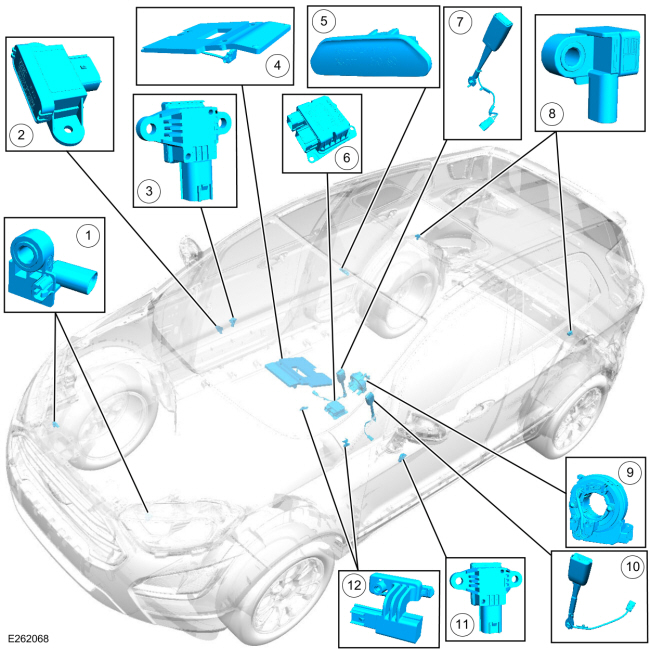
| Item | Description |
|---|---|
| 1 | LH and RH front impact severity sensors |
| 2 | BECMB |
| 3 | Passenger front door side impact sensor |
| 4 | OCSM (includes OCS sensor and gel-filled bladder) |
| 5 | PAD indicator |
| 6 | RCM |
| 7 | Front passenger seatbelt buckle (includes buckle sensor) |
| 8 | Driver and passenger side C-pillar side impact sensors |
| 9 | Clockspring |
| 10 | Driver seatbelt buckle (includes buckle sensor) |
| 11 | Driver front door side impact sensor |
| 12 | Driver and passenger seat position sensors |
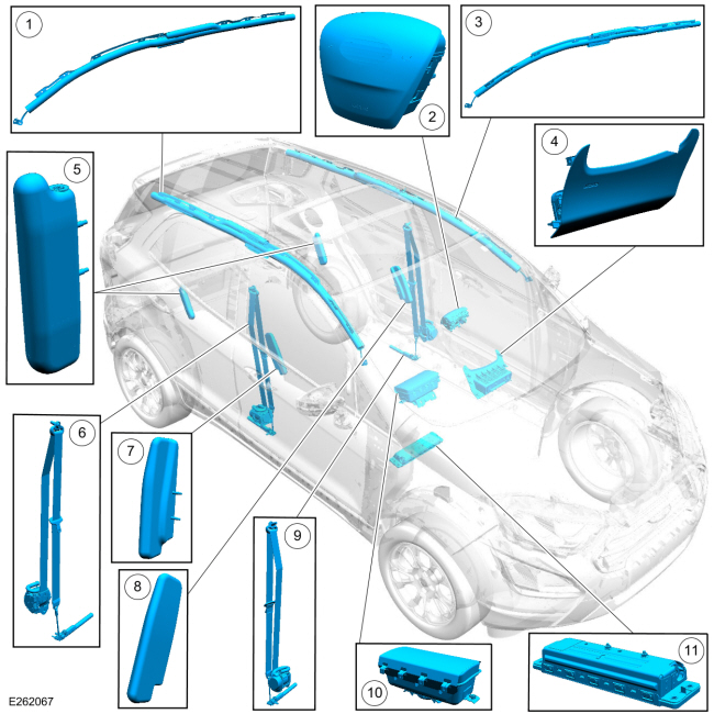
| Item | Description |
|---|---|
| 1 | RH side air curtain |
| 2 | Driver airbag |
| 3 | LH side air curtain |
| 4 | Driver knee airbag |
| 5 | LH and RH rear side airbags |
| 6 | Front passenger seatbelt retractor (includes retractor pretensioner, adaptive load limiter and anchor pretensioner) |
| 7 | Passenger side airbag |
| 8 | Driver side airbag |
| 9 | Driver seatbelt retractor (includes retractor pretensioner and anchor pretensioner) |
| 10 | Passenger airbag (includes canister vent) |
| 11 | Passenger knee airbag |

 Description and Operation - Airbag and Seatbelt Pretensioner
Supplemental Restraint System (SRS) - Vehicles With: Rear Seat Side
Airbag - Overview
Description and Operation - Airbag and Seatbelt Pretensioner
Supplemental Restraint System (SRS) - Vehicles With: Rear Seat Side
Airbag - Overview
Overview
The RCM continually receives and monitors inputs from the OCSM ,
BECMB and various other hard-wired switches and sensors. If the RCM
detects a sudden vehicle deceleration and/or lateral deceleration
based on the information received from the various sensors, and
determines that deployment is necessary, the RCM applies voltage and
current to deploy the appropriate SRS component..
Other information:
Ford Ecosport 2014-2025 Service and Repair Manual: Removal and Installation - Brake Pads
Special Tool(s) / General Equipment 206-005Retractor, Brake Caliper Piston Materials Name Specification Motorcraft® DOT 4 LV High Performance Motor Vehicle Brake FluidPM-20 WSS-M6C65-A2 Motorcraft® Metal Brake Parts CleanerPM-4-A, PM-4-B, APM-4-C - Removal NOTE: Removal steps in this procedure may contain installa..
Ford Ecosport 2014-2025 Service and Repair Manual: Specifications
Lubricants, Fluids, Sealers and Adhesives Specifications Motorcraft® MERCON® LV Automatic Transmission Fluid XT-10-QLVC MERCON® LV If the transmission fluid does not drain from the oil leveling plug hole, add transmission fluid in increments of 0.25 L/0.26 qts (at opera..
Categories
- Manuals Home
- 2nd Gen Ford Ecosport Service Manual (2014 - 2025)
- Removal and Installation - Catalytic Converter
- Automatic Transmission - 6-Speed Automatic Transmission – 6F35
- Diagnosis and Testing - Body Control Module (BCM)
- Body and Paint
- Removal and Installation - Blower Motor
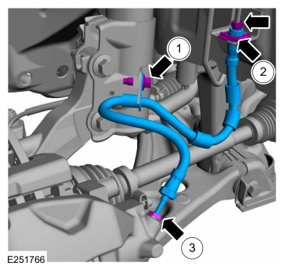
Removal and Installation - Front Brake Flexible Hose
Removal
Remove the wheel and tire.Refer to: Wheel and Tire (204-04A Wheels and Tires, Removal and Installation).
Remove the brake flexible hose bracket bolt.
Disconnect the brake tube fitting and remove the brake hose clip.
Loosen the brake hose fitting and remove the brake flexible hose.
Copyright © 2025 www.foecosport2.com