
Ford Ecosport: Steering Column / Removal and Installation - Steering Wheel
Ford Ecosport 2014-2026 Service and Repair Manual / Steering System / Steering Column / Removal and Installation - Steering Wheel
Special Tool(s) / General Equipment
| Adhesive Tape |
Removal
NOTE: Removal steps in this procedure may contain installation details.
-
Remove the driver air bag.
Refer to: Driver Airbag (501-20B Supplemental Restraint System, Removal and Installation).
-
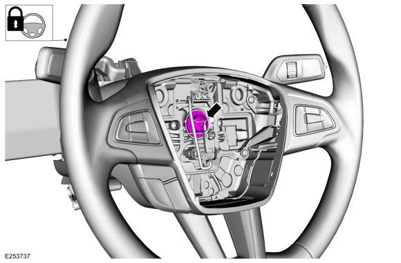
NOTICE: Make sure that the steering wheel lock is engaged.
NOTE: Make sure that the road wheels are in the straight ahead position.
Remove the steering wheel bolt.
Torque: 30 lb.ft (40 Nm)
 |
-
-
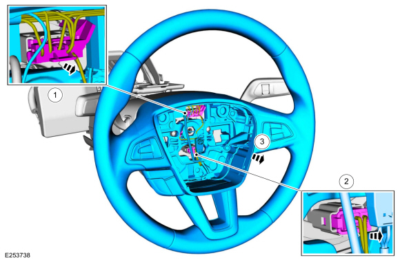
Disconnect the upper electrical connector.
-
Disconnect the lower electrical connector.
-
Remove the steering wheel.
-
Disconnect the upper electrical connector.
 |
-
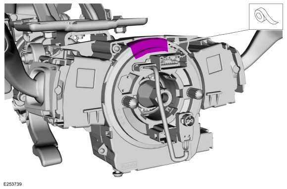
NOTICE: Make sure that the clockspring rotor does not rotate.
NOTICE: Make sure that the clockspring pins are not bent or damaged.
Secure the clockspring with adhesive tape.
Use the General Equipment: Adhesive Tape
 |
Installation
-
To install, reverse the removal procedure.
 Removal and Installation - Steering Column Shaft
Removal
NOTE:
Removal steps in this procedure may contain installation details.
NOTICE:
Do not allow the steering column to rotate while the
steering column shaft is disconnected or damage to the steering column
internal sensor may result...

Other information:
Ford Ecosport 2014-2026 Service and Repair Manual: Description and Operation - Perimeter Anti-Theft Alarm - Overview
Overview The perimeter anti-theft alarm system has three operation modes: ARMED - The perimeter anti-theft alarm is armed when the ignition is OFF and all vehicle entry points have been electrically locked for 20 seconds. ACTIVE - When the perimeter anti-theft alarm activates, the horn sounds and all turn signals and interior courtesy lamps flash. The horn stops soundin..
Ford Ecosport 2014-2026 Service and Repair Manual: Diagnosis and Testing - Pinpoint Test - DTC: AL, Vehicles With: Rear Seat Side Airbag
B1142:62, B11D9:13, B13BF:14 Refer to Wiring Diagrams Cell 46 for schematic and connector information. Normal Operation and Fault Conditions The BECMB provides battery voltage to the RCM and OCSM . The BECMB compares HS-CAN1 messages to ignition voltage inputs. If the status of the HS-CAN1 message and the voltage input do not match, the BECMB sets a DTC . If a fault is de..
Categories
- Manuals Home
- 2nd Gen Ford Ecosport Service Manual (2014 - 2026)
- Removal and Installation - Catalytic Converter
- Removal and Installation - Body Control Module (BCM)
- Body and Paint
- Specifications
- Removal and Installation - Blower Motor
Removal and Installation - Steering Column Shaft
Removal
NOTE: Removal steps in this procedure may contain installation details.
NOTICE: Do not allow the steering column to rotate while the steering column shaft is disconnected or damage to the steering column internal sensor may result.
NOTE: Use a steering wheel holding device (such as Hunter® 28-75-1 or equivalent)
Hold the steering wheel in the straight-ahead position.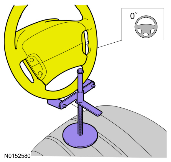

Copyright © 2026 www.foecosport2.com