
Ford Ecosport: Automatic Transmission External Controls / Removal and Installation - Selector Lever Bezel
Ford Ecosport 2014-2026 Service and Repair Manual / Automatic Transmission / Automatic Transmission External Controls / Removal and Installation - Selector Lever Bezel
Special Tool(s) / General Equipment
| Interior Trim Remover |
Removal
All vehicles
-
Remove the selector lever knob.
Refer to: Selector Lever Knob (307-05 Automatic Transmission External Controls, Removal and Installation).
Selector lever knobs without a SelectShift® switch
-
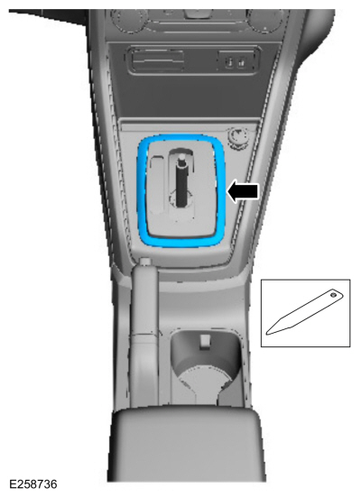
Remove the selector lever bezel trim ring.
Use the General Equipment: Interior Trim Remover
 |
-
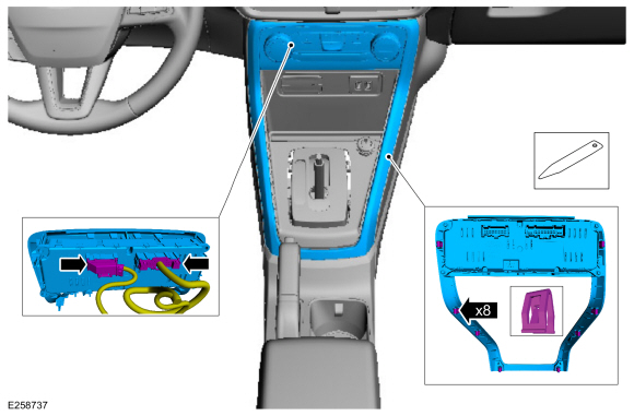
Detach the trim ring and the HVAC control module, disconnect the HVAC
control module electrical connectors and remove the trim ring and the
HVAC control module as an assembly.
Use the General Equipment: Interior Trim Remover
 |
-
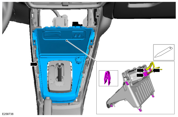
Remove the selector lever finish panel and disconnect the electrical connectors.
Use the General Equipment: Interior Trim Remover
 |
All vehicles
-
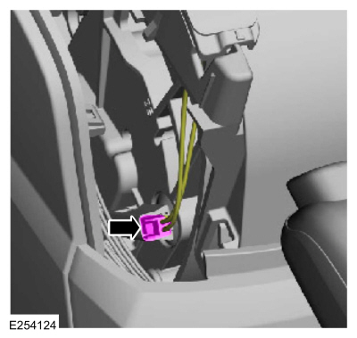
Disconnect the LED strip electrical connector.
 |
-
Remove the selector lever bezel.
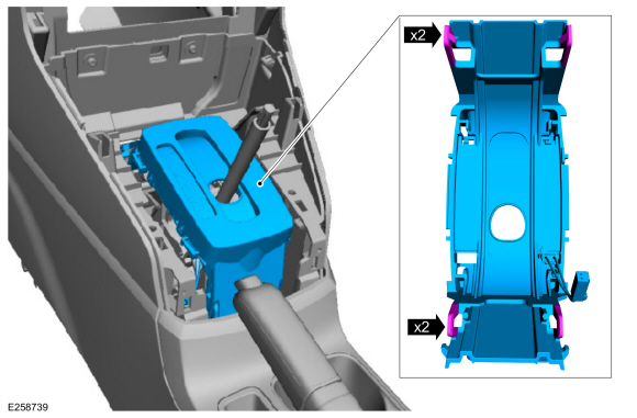 |
Installation
-
To install, reverse the removal procedure.
 Removal and Installation - Selector Lever
Removal
NOTE:
Removal steps in this procedure may contain installation details.
Remove the floor console.
Refer to: Floor Console (501-12 Instrument Panel and Console, Removal and Installation)...
 Removal and Installation - Selector Lever Knob
Special Tool(s) /
General Equipment
Interior Trim Remover
Removal
All vehicles
Apply the parking brake.
Position the selector lever in S ...
Other information:
Ford Ecosport 2014-2026 Service and Repair Manual: Removal and Installation - Driveshaft
Special Tool(s) / General Equipment Flat Headed Screw Driver Center Punch Copper Hammer Removal NOTE: The max articulation of any CV is 5 degrees. If the CV or any U-joint of the driveshaft is articulated further then the max allowable degrees damage may occur...
Ford Ecosport 2014-2026 Service and Repair Manual: General Procedures - Clockspring Adjustment
Special Tool(s) / General Equipment Adhesive Tape WARNING: If the clockspring is not correctly centralized, it may fail prematurely. If in doubt, repeat the centralizing procedure. Failure to follow these instructions may increase the risk of serious personal injury or death in a crash...
Categories
- Manuals Home
- 2nd Gen Ford Ecosport Service Manual (2014 - 2026)
- Removal and Installation - Rear Bumper
- Removal and Installation - Catalytic Converter
- Removal and Installation - Body Control Module (BCM)
- General Procedures - Battery Charging
- Removal and Installation - Fuel Pump and Sender Unit
Description and Operation - Health and Safety Precautions
General Service Warnings
Review carefully the information below before beginning any repair. Following these warnings is a list of specific system warnings that must be reviewed before beginning work on any listed system.
 WARNING:
Wear eye and ear protection when servicing a vehicle.
Failure to follow this instruction may result in serious personal
injury.
WARNING:
Wear eye and ear protection when servicing a vehicle.
Failure to follow this instruction may result in serious personal
injury.

Copyright © 2026 www.foecosport2.com