Ford Ecosport: Information and Entertainment System - General Information / Removal and Installation - Instrument Panel Center Speaker
Ford Ecosport 2014-2026 Service and Repair Manual / Information and Entertainment Systems / Information and Entertainment System - General Information / Removal and Installation - Instrument Panel Center Speaker
Special Tool(s) / General Equipment
| Interior Trim Remover |
Removal
NOTE: Removal steps in this procedure may contain installation details.
NOTE: 8 inch display is shown, all other displays are similar.
-
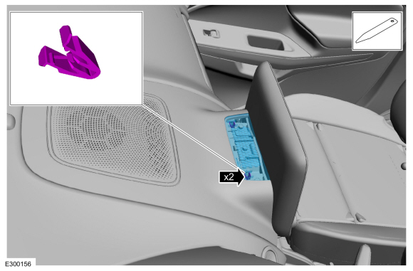
Release the clips and remove the screw cover trim panel.
Use the General Equipment: Interior Trim Remover
 |
-
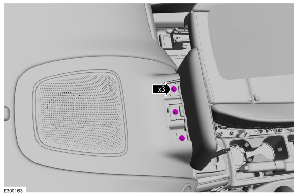
Remove the screws.
 |
-
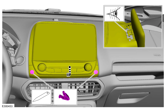
Release the clips, position the FDIM up until the locating tabs are above the mounting bracket.
 |
-
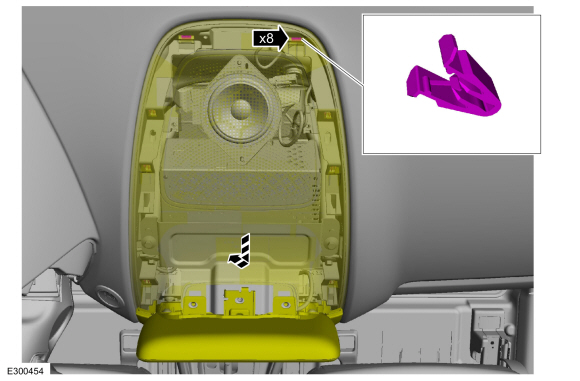
Release the clips and position the instrument panel top center trim panel forward and up.
 |
-
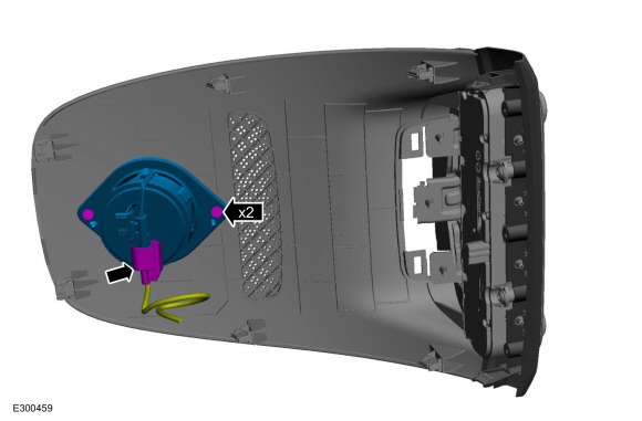
Disconnect the electrical connector and remove the screws and the instrument panel center speaker.
 |
Installation
-
To install, reverse the removal procedure.
 Removal and Installation - Front Door Tweeter Speaker
Removal
NOTE:
Removal steps in this procedure may contain installation details.
Remove the interior front door handle.
Refer to: Interior Front Door Handle (501-14 Handles, Locks, Latches and Entry Systems, Removal and Installation)...
 Removal and Installation - Low Voltage Differential Signalling (LVDS) Cable
Removal
Remove the components for access.
Remove the IPC .
Refer to: Instrument Panel Cluster (IPC) (413-01 Instrumentation, Message Center and Warning Chimes, Removal and Installation)...
Other information:
Ford Ecosport 2014-2026 Service and Repair Manual: Description and Operation - Steering Wheel and Column Electrical Components - Overview
Steering Column Switches Overview The steering column switches are located on and around the steering column. They enable the driver to control various vehicle functions while remaining focused on driving. The steering column switches consist of: Left multifunction switch - mounted on the left side of the SCCM and is used: to control the turn signals, low/high beam selectio..
Ford Ecosport 2014-2026 Service and Repair Manual: General Procedures - Battery Disconnect and Connect
Special Tool(s) / General Equipment Adhesive Tape Disconnect NOTE: When the battery is disconnected and connected, some abnormal drive symptoms may occur while the vehicle relearns its adaptive strategy. The vehicle may need to be driven to allow the PCM to relearn the adaptive strategy values. NOTE: When disconnecting the battery ground cable to interrupt po..
Categories
- Manuals Home
- 2nd Gen Ford Ecosport Service Manual (2014 - 2026)
- Removal and Installation - Roof Rail
- Removal and Installation - Fuel Pump and Sender Unit
- Removal and Installation - Starter Motor
- Description and Operation - Evaporative Emissions - System Operation and Component Description
- Removal and Installation - Front Seat
Removal and Installation - Steering Column Shaft
Removal
NOTE: Removal steps in this procedure may contain installation details.
NOTICE: Do not allow the steering column to rotate while the steering column shaft is disconnected or damage to the steering column internal sensor may result.
NOTE: Use a steering wheel holding device (such as Hunter® 28-75-1 or equivalent)
Hold the steering wheel in the straight-ahead position.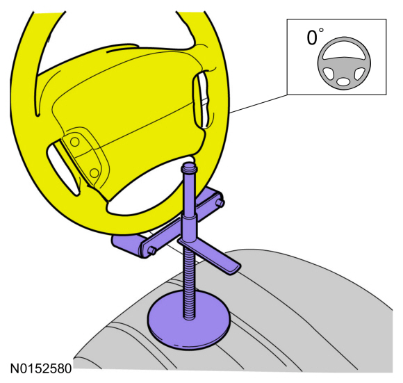
Copyright © 2026 www.foecosport2.com