Ford Ecosport: Module Communications Network / Removal and Installation - Gateway Module A (GWM)
Ford Ecosport 2014-2026 Service and Repair Manual / Electrical Distribution / Module Communications Network / Removal and Installation - Gateway Module A (GWM)
Removal
NOTE: Removal steps in this procedure may contain installation details.
-
NOTE: If installing a new module, it is necessary to upload the module configuration information to the scan tool prior to removing the module. This information must be downloaded into the new module after installation.
Using a diagnostic scan tool, begin the PMI process for the GWM following the on-screen instructions.
-
Remove the screws and position the GWM down.
Torque: 27 lb.in (3 Nm)
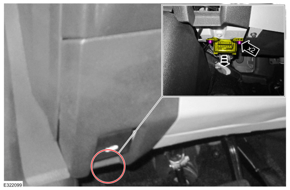 |
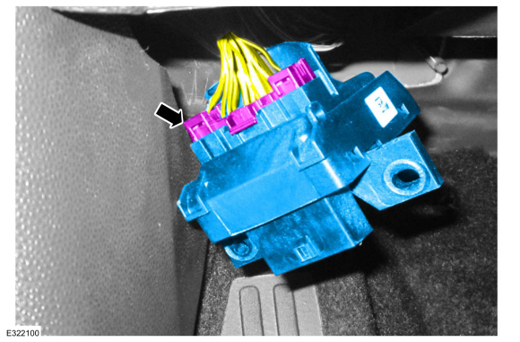
-
Disconnect the electrical connector and remove the GWM .
 |
Installation
-
To install, reverse the removal procedure.
-
Using a diagnostic scan tool, complete the PMI process for the GWM following the on-screen instructions.
 Diagnosis and Testing - Communications Network
Diagnostic Trouble Code (DTC) Chart
Diagnostics in this manual assume a certain skill level and knowledge of Ford-specific diagnostic practices. REFER to: Diagnostic Methods (100-00 General Information, Description and Operation)...

Other information:
Ford Ecosport 2014-2026 Service and Repair Manual: Removal and Installation - Rear Floor Panel Section
Special Tool(s) / General Equipment Resistance Spotwelding Equipment Scraper for Straight Edges Spherical Cutter Hot Air Gun Air Body Saw 8 mm Drill Bit MIG/MAG Welding Equipment Spot Weld Drill Bit Materials Name Specification Seam SealerTA-2-B, 3M™ 08308, LORD Fusor® 803DTM - Removal ..
Ford Ecosport 2014-2026 Service and Repair Manual: Diagnosis and Testing - Electronic Throttle Control System
Diagnostic Trouble Code (DTC) Chart Diagnostics in this manual assume a certain skill level and knowledge of Ford-specific diagnostic practices.REFER to: Diagnostic Methods (100-00 General Information, Description and Operation). Module DTC Description Action PCM P0068:00 MAP / MAF - Throttle Position Correlation: No Sub Type Information GO to Pinpoint Test DV ..
Categories
- Manuals Home
- 2nd Gen Ford Ecosport Service Manual (2014 - 2026)
- Description and Operation - Evaporative Emissions - System Operation and Component Description
- Automatic Transmission - 6-Speed Automatic Transmission – 6F35
- Description and Operation - Jacking and Lifting - Overview
- Body and Paint
- Removal and Installation - Evaporative Emission Canister Purge Valve
Disassembly - Engine
Special Tool(s) / General Equipment
 205-153
(T80T-4000-W)
205-153
(T80T-4000-W)
Handle
 303-103
(T74P-6375-A)
303-103
(T74P-6375-A)
Holding Tool, Flywheel
T74P-77000-A
TKIT-2009TC-F
 303-1247
VCT Spark Plug Tube Seal Remover and Installer
TKIT-2006UF-FLM
TKIT-2006UF-ROW
 303-15
Copyright © 2026 www.foecosport2.com