Ford Ecosport: Hydraulic Brake Actuation / Removal and Installation - Brake Master Cylinder
Ford Ecosport 2014-2026 Service and Repair Manual / Brake System / Hydraulic Brake Actuation / Removal and Installation - Brake Master Cylinder
Materials
| Name | Specification |
|---|---|
| Motorcraft® DOT 4 LV High Performance Motor Vehicle Brake Fluid PM-20 |
WSS-M6C65-A2 |
Removal
NOTE: Removal steps in this procedure may contain installation details.
NOTE: LHD shown, RHD similar.
Left hand drive (LHD) vehicles
-
Remove the battery tray.
Refer to: Battery Tray (414-01 Battery, Mounting and Cables, Removal and Installation).
All vehicles
-
-
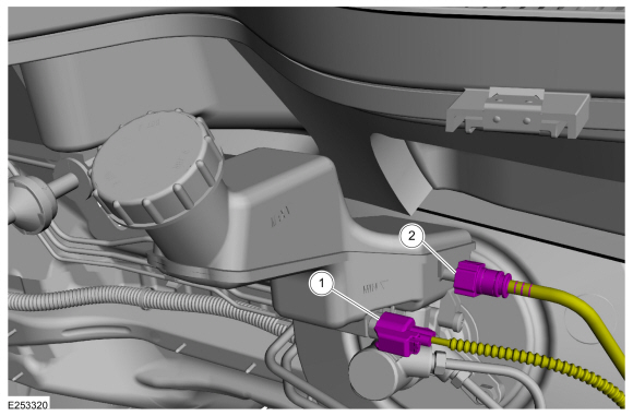
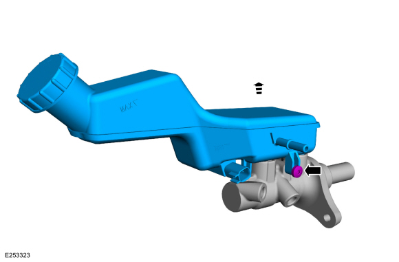
Disconnect the brake fluid level sensor electrical connector.
-
NOTICE: Make sure that all openings are sealed.
If equipped.
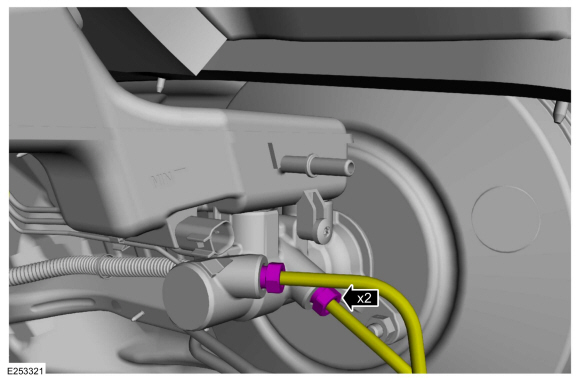
Disconnect the clutch master cylinder tube.
-
Disconnect the brake fluid level sensor electrical connector.
 |
-
NOTICE: Make sure that all openings are sealed.
Disconnect the brake tube fittings.
Torque: 159 lb.in (18 Nm)
 |
-
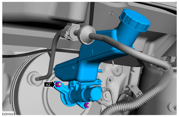
Remove the nuts and the brake master cylinder.
Torque: 18 lb.ft (25 Nm)
 |
-
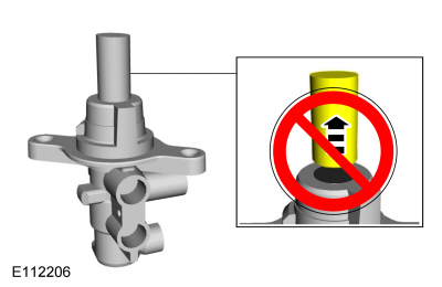
NOTICE: Take extra care when handling the components.
Do not remove the brake master cylinder piston extension.
 |
-
If a new brake master cylinder is being installed.
Remove the pin and the brake fluid reservoir.
Torque: 44 lb.in (5 Nm)
 |
Installation
-
NOTE: Install new brake fluid reservoir seals. Lubricate the seals with clean, specified brake fluid.
To install, reverse the removal procedure.
Material: Motorcraft® DOT 4 LV High Performance Motor Vehicle Brake Fluid / PM-20 (WSS-M6C65-A2)
-
-
If a new brake master cylinder has been installed, bleed the brake master cylinder.
Refer to: Component Bleeding (206-00 Brake System - General Information, General Procedures).
-
If the brake master cylinder was removed to access other components, bleed the brake system.
Refer to: Brake System Pressure Bleeding (206-00 Brake System - General Information, General Procedures).
-
If a new brake master cylinder has been installed, bleed the brake master cylinder.
-
If equipped with manual transmission.
Bleed the clutch system.
Refer to: Clutch System Bleeding (308-02 Clutch Controls - 5-Speed Manual Transmission – B5/IB5, General Procedures).

 Removal and Installation - Brake Pedal and Bracket
Special Tool(s) /
General Equipment
Flat-Bladed Screwdriver
Removal
NOTE:
Removal steps in this procedure may contain installation details...
Other information:
Ford Ecosport 2014-2026 Service and Repair Manual: Description and Operation - Blind Spot Information System - Overview
Overview BLIS ® The BLIS ® aids the driver in assessing whether another vehicle is present within a specific area (blind spot) to either side of the vehicle, extending rearward approximately 4 m (13 ft) beyond the rear bumper while driving on roads and highways...
Ford Ecosport 2014-2026 Service and Repair Manual: Specifications
RDU Lubricant Specification Capacity Motorcraft® SAE 80W-90 Premium Rear Axle Lubricant XY-80W90-QL (US); CXY-80W90-1L (Canada) Material: Motorcraft® SAE 80W-90 Premium Rear Axle Lubricant / XY-80W90-QL (WSP-M2C197-A) 0...
Categories
- Manuals Home
- 2nd Gen Ford Ecosport Service Manual (2014 - 2026)
- Diagnosis and Testing - Evaporative Emissions
- Removal and Installation - Front Seat
- Service Information
- Removal and Installation - Fuel Pump and Sender Unit
- Removal and Installation - Starter Motor
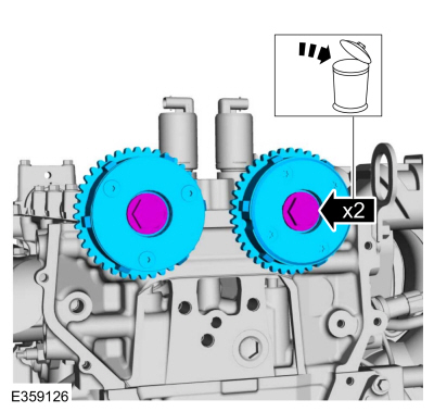
Removal and Installation - Variable Camshaft Timing (VCT) Unit
Removal
NOTICE: During engine repair procedures, cleanliness is extremely important. Any foreign material, including any material created while cleaning gasket surfaces, that enters the oil passages, coolant passages or the oil pan can cause engine failure.
Remove the timing chain.Refer to: Timing Chain (303-01C Engine - 2.0L Duratec-HE (129kW/175PS), Removal and Installation).
Remove the bolts and VCT units.
Discard the bolts.
Copyright © 2026 www.foecosport2.com