Ford Ecosport: Exterior Lighting / Diagnosis and Testing - Autolamps
DTC Chart: BCM
Diagnostics in this manual assume a certain skill level and knowledge of Ford-specific diagnostic practices.
REFER to: Diagnostic Methods (100-00 General Information, Description and Operation).
BCM DTC Chart
| DTC | Description | Action |
|---|---|---|
| B1A85:11 | Ambient Light Sensor: Circuit Short To Ground | GO to Pinpoint Test A |
| B1A85:13 | Ambient Light Sensor: Circuit Open | GO to Pinpoint Test A |
| For other BCM Diagnostic Trouble Codes (DTCs) | - |
REFER to: Body Control Module (BCM) (419-10 Multifunction Electronic Modules, Diagnosis and Testing). |
Symptom Chart(s)
Diagnostics in this manual assume a certain skill level and knowledge of Ford-specific diagnostic practices.
REFER to: Diagnostic Methods (100-00 General Information, Description and Operation).
Symptom Chart: Autolamps
Symptom Chart
| Condition | Possible Sources | Actions |
|---|---|---|
| A module does not respond to the diagnostic scan tool |
|
REFER to: Communications Network (418-00 Module Communications Network) . |
| The autolamps are inoperative/do not operate correctly | Refer to the Pinpoint Test | GO to Pinpoint Test A |
Pinpoint Tests
|
Refer to Wiring Diagrams Cell 85 for schematic and connector information. Normal Operation and Fault Conditions
REFER to: Exterior Lighting - Overview (417-01 Exterior Lighting, Description and Operation).
REFER to: Exterior Lighting - Overview (417-01 Exterior Lighting, Description and Operation). DTC Fault Trigger Conditions
Possible Sources
Visual Inspection and Pre-checks
|
||||||||||||||||
| A1 CHECK THE MANUAL HEADLAMP OPERATION | ||||||||||||||||
Do the headlamps operate correctly?
|
||||||||||||||||
| A2 CHECK FOR VOLTAGE TO THE LIGHT SENSOR | ||||||||||||||||
Is the voltage approximately 5 volts?
|
||||||||||||||||
| A3 CHECK THE LIGHT SENSOR FOR GROUND | ||||||||||||||||
Is the voltage approximately 5 volts?
|
||||||||||||||||
| A4 CHECK THE LIGHT SENSOR GROUND CIRCUIT FOR AN OPEN | ||||||||||||||||
Is the resistance less than 3 ohms?
|
||||||||||||||||
| A5 CHECK THE LIGHT SENSOR INPUT CIRCUIT FOR A SHORT TO GROUND | ||||||||||||||||
Is the resistance greater than 10,000 ohms?
|
||||||||||||||||
| A6 CHECK THE LIGHT SENSOR INPUT CIRCUIT FOR AN OPEN | ||||||||||||||||
Is the resistance less than 3 ohms?
|
||||||||||||||||
| A7 CHECK THE LIGHT SENSOR INPUT CIRCUIT FOR A SHORT TO VOLTAGE | ||||||||||||||||
Is any voltage present?
|
||||||||||||||||
| A8 CHECK FOR CORRECT BCM (BODY CONTROL MODULE) OPERATION | ||||||||||||||||
Is the concern still present?
|


 Diagnosis and Testing - Reversing Lamps
DTC Chart: BCM
Diagnostics in this manual assume a certain skill level and knowledge of Ford-specific diagnostic practices. REFER to: Diagnostic Methods (100-00 General Information, Description and Operation)...
 Diagnosis and Testing - Stoplamps
DTC Chart: BCM
Diagnostics in this manual assume a certain skill level and knowledge of Ford-specific diagnostic practices. REFER to: Diagnostic Methods (100-00 General Information, Description and Operation)...
Other information:
Ford Ecosport 2014-2026 Service and Repair Manual: Removal and Installation - Cabin Heater Coolant Pump - 2.0L Duratec-HE (129kW/175PS)
Special Tool(s) / General Equipment Hose Clamp(s) Removal NOTE: Removal steps in this procedure may contain installation details. Remove the battery tray. Refer to: Battery Tray (414-01 Battery, Mounting and Cables, Removal and Installation)...
Ford Ecosport 2014-2026 Service and Repair Manual: Removal and Installation - Fuel Pump and Sender Unit
Special Tool(s) / General Equipment 310-123Locking Ring, Fuel TankTKIT-2004J-FTKIT-2005U-LM Removal NOTE: Removal steps in this procedure may contain installation details. Remove the Fuel Tank. Refer to: Fuel Tank (310-01C Fuel Tank and Lines - 2...
Categories
- Manuals Home
- 2nd Gen Ford Ecosport Service Manual (2014 - 2026)
- General Procedures - Battery Charging
- Description and Operation - Evaporative Emissions - System Operation and Component Description
- General Procedures - Transmission Fluid Level Check
- Removal and Installation - Roof Rail
- Removal and Installation - Front Seat
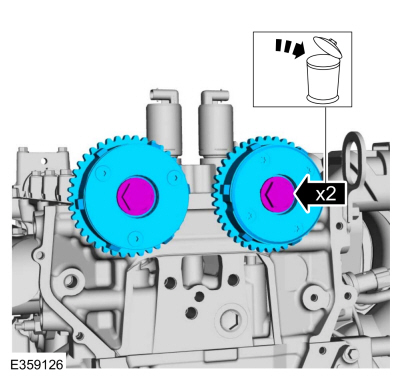
Removal and Installation - Variable Camshaft Timing (VCT) Unit
Removal
NOTICE: During engine repair procedures, cleanliness is extremely important. Any foreign material, including any material created while cleaning gasket surfaces, that enters the oil passages, coolant passages or the oil pan can cause engine failure.
Remove the timing chain.Refer to: Timing Chain (303-01C Engine - 2.0L Duratec-HE (129kW/175PS), Removal and Installation).
Remove the bolts and VCT units.
Discard the bolts.