Ford Ecosport: Driveshaft / Removal and Installation - Driveshaft
Special Tool(s) / General Equipment
| Flat Headed Screw Driver | |
| Center Punch | |
| Copper Hammer |
Removal
NOTE: The max articulation of any CV is 5 degrees. If the CV or any U-joint of the driveshaft is articulated further then the max allowable degrees damage may occur.
NOTE: Removal steps in this procedure may contain installation details.
-
With the vehicle in NEUTRAL, position it on a hoist.
Refer to: Jacking and Lifting - Overview (100-02 Jacking and Lifting, Description and Operation).
-
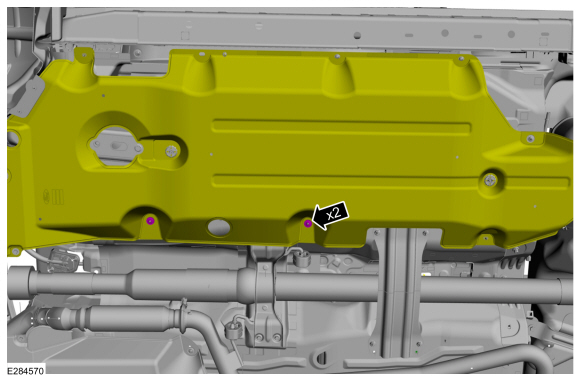
If equipped.
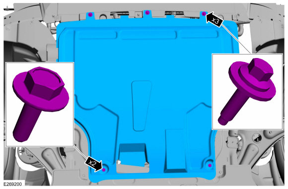
Remove the retainers and the under body shield.
Torque:
1: 42 lb.in (4.8 Nm)
2: 17 lb.in (1.9 Nm)
 |
-
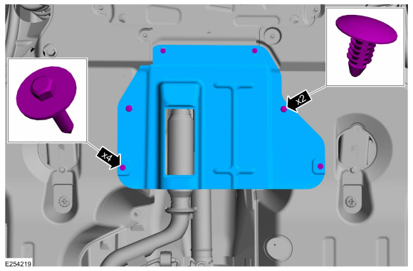
If equipped.
Remove the retainers and the under body air deflector shield.
 |
-
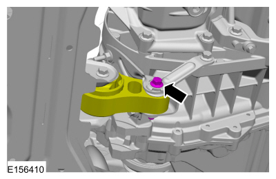
Remove the bolt for the transmission mount.
Torque: 52 lb.ft (70 Nm)
 |
-
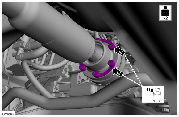
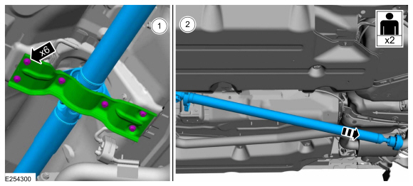
NOTE: The installation step requires the aid of another technician.
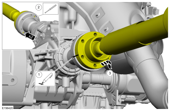
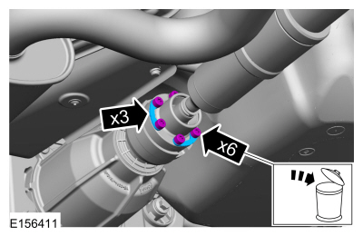
Remove and discard the driveshaft to PTU bolt and the retaining straps.
Torque: 26 lb.ft (35 Nm)
 |
-
Separate the driveshaft from the PTU flange.
-
Index-mark the driveshaft and PTU flange.
-
NOTE: Do not remove driveshaft from the PTU flange by pulling on the driveshaft tube. Damage to the CV-joint can result.
NOTE: This is a tight fit, do not remove the CV flange from the PTU flange at this time.
Using general equipments, separate the driveshaft from the PTU flange.
Use the General Equipment: Center Punch
Use the General Equipment: Copper Hammer
-
Remove the driveshaft from the PTU flange.
-
Index-mark the driveshaft and PTU flange.
 |
-
Remove and discard the driveshaft to RDU bolt and the retaining straps.
Torque: 26 lb.ft (35 Nm)
 |
-
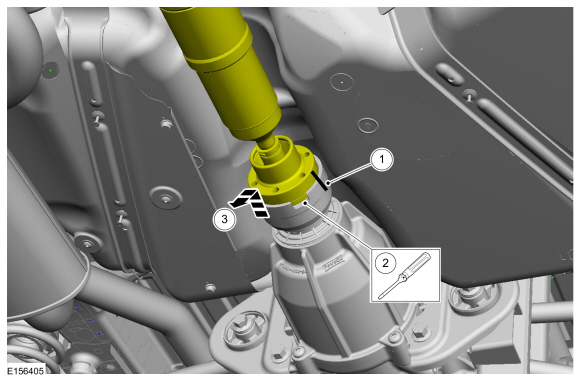
Separate the driveshaft from the drive pinion flange.
-
NOTE: Make sure that the component aligns with the installation mark.
Index-mark the driveshaft and RDU flange.
-
NOTE: Do not remove driveshaft from the pinion flange by pulling on the driveshaft tube. Damage to the CV-joint can result.
Using general equipment, separate the driveshaft from the RDU flange.
Use the General Equipment: Flat Headed Screw Driver
-
Remove the driveshaft from the RDU flange.
-
 |
-
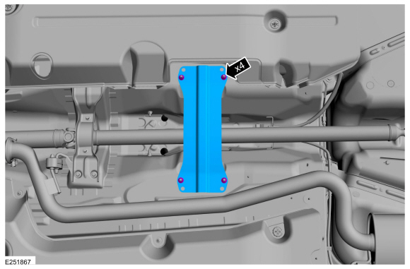
Remove the nuts and the rear cross member.
Torque: 18 lb.ft (25 Nm)
 |
-
Remove the aero deflector shield stamped nuts.
 |
-
NOTICE: Do not over articulate the driveshaft or damage may occur.
NOTICE: The driveshaft is long and heavy with multiple CV-joints. The help of a assistant will be needed. Do not over articulate the driveshaft or damage may occur.
NOTE: Do not allow the angle of the driveshaft CV joints exceed 5 degrees.
-
Remove the bolts and the center bearing bracket.
Torque: 18 lb.ft (25 Nm)
-
NOTE: When installing the driveshaft, it will be necessary to place the CV joint flanges of the driveshaft into the PTU and RDU flanges before installing the center bearing bolts.
With the help of an assistant, remove the driveshaft.
-
Remove the bolts and the center bearing bracket.
 |
Installation
-
NOTE: If a driveshaft is installed and driveshaft vibration is encountered after installation, index the driveshaft.
To install, reverse the removal procedure.
 General Procedures - Driveshaft Runout and Balancing
Special Tool(s) /
General Equipment
100-002
(TOOL-4201-C)
Holding Fixture with Dial Indicator Gauge
Inspection
NOTE:
Driveline vibration exhibits a higher frequency and lower
amplitude then high-speed shake...

Other information:
Ford Ecosport 2014-2026 Service and Repair Manual: Diagnosis and Testing - Transmission Cooling
Inspection and Verification Verify the customer concern. Visually inspect for obvious signs of mechanical or electrical damage. If an obvious cause for an observed or reported concern is found, correct the cause (if possible) before proceeding to the next step If the cause is not visually evident, verify the symptom and refer to the Symptom Chart...
Ford Ecosport 2014-2026 Service and Repair Manual: Removal and Installation - Rear Door Window Glass
Removal NOTE: LH side shown, RH side similar. Remove the rear door glass run and bracket. Refer to: Rear Door Glass Run and Bracket (501-11 Glass, Frames and Mechanisms, Removal and Installation). Remove the rear door glass top run. Refer to: Rear Door Glass Top Run (501-11 Glass, Frames and Mechanisms, Removal and Installation). ..
Categories
- Manuals Home
- 2nd Gen Ford Ecosport Service Manual (2014 - 2026)
- Diagnosis and Testing - Evaporative Emissions
- Removal and Installation - Rear Bumper
- Removal and Installation - Evaporative Emission Canister Purge Valve
- Description and Operation - Evaporative Emissions - System Operation and Component Description
- Automatic Transmission - 6-Speed Automatic Transmission – 6F35
Removal and Installation - Front Stabilizer Bar
Special Tool(s) / General Equipment
Tie Rod End Remover Transmission JackRemoval
NOTICE: Suspension fasteners are critical parts that affect the performance of vital components and systems. Failure of these fasteners may result in major service expense. Use the same or equivalent parts if replacement is necessary. Do not use a replacement part of lesser quality or substitute design. Tighten fasteners as specified.
NOTE: Removal steps in this procedure may contain installation details.
NOTICE: Disconnect the b