Ford Ecosport: Engine Emission Control - 2.0L Duratec-HE (129kW/175PS) / Description and Operation - Engine Emission Control
| Item | Part Number | Description |
|---|---|---|
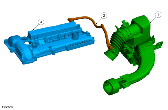
| 1 | — | Air cleaner assembly |
| 2 | — | Positive crankcase ventilation (PCV) hose from valve cover to air cleaner outlet pipe |
| 3 | — | Valve cover |
| Item | Part Number | Description |
|---|---|---|
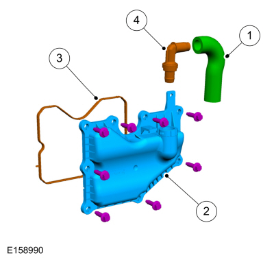
| 1 | — | PCV valve to intake manifold PCV hose |
| 2 | — | Crankcase vent oil separator |
| 3 | — | Crankcase vent oil separator gasket |
| 4 | — | PCV valve |
Positve Crankcase Ventilation (PCV) System
The PCV system consists of a valve mounted in the crankcase vent oil separator (attached to the cylinder block) and two hoses.
One PCV hose connects the PCV valve to the intake manifold, the other PCV hose connects the valve cover to the air cleaner outlet pipe.
Under idle and part throttle conditions, the crankcase vapor flows from the crankcase vent oil separator to the intake manifold and into the combustion chambers where the vapor is burnt during combustion.
Under full throttle conditions, the crankcase vapor flows from the valve cover into the air cleaner outlet pipe through the PCV hose.

 Description and Operation - Engine Emission Control - System Operation and Component Description
System Operation
Positive Crankcase Ventilation (PCV) System
The PCV system circulates crankcase gases through the intake air
system into the engine where they are burned...
Other information:
Ford Ecosport 2014-2026 Service and Repair Manual: Removal and Installation - Instrument Panel Upper Section
Removal NOTE: Removal steps in this procedure may contain installation details. Remove the instrument panel. Refer to: Instrument Panel (501-12 Instrument Panel and Console, Removal and Installation). Remove the ACM ...
Ford Ecosport 2014-2026 Service and Repair Manual: Removal and Installation - Loadspace Trim Panel
Removal NOTE: RH shown, LH similar. NOTE: Removal steps in this procedure may contain installation details. Remove the D-pillar trim panel. Refer to: D-Pillar Trim Panel (501-05 Interior Trim and Ornamentation, Removal and Installation)...
Categories
- Manuals Home
- 2nd Gen Ford Ecosport Service Manual (2014 - 2026)
- Removal and Installation - Body Control Module (BCM)
- Engine
- Description and Operation - Evaporative Emissions - System Operation and Component Description
- Description and Operation - Jacking and Lifting - Overview
- General Procedures - Battery Charging
Removal and Installation - Steering Column Shaft
Removal
NOTE: Removal steps in this procedure may contain installation details.
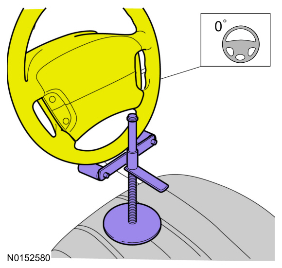
NOTICE: Do not allow the steering column to rotate while the steering column shaft is disconnected or damage to the steering column internal sensor may result.
NOTE: Use a steering wheel holding device (such as Hunter® 28-75-1 or equivalent)
Hold the steering wheel in the straight-ahead position.